Protection enclosure of portable electronic device

a protection enclosure and electronic device technology, applied in the field of accessories of portable electronic devices, can solve the problems of easy slipping, undesired inconvenience, difficult control and fixation of the angle position, etc., and achieve the effects of convenient use and operation, easy slipping, and easy control and fixation

Inactive Publication Date: 2018-04-03
KUO KUO TANG
View PDF2 Cites 8 Cited by
  • Summary
  • Abstract
  • Description
  • Claims
  • Application Information

AI Technical Summary

Benefits of technology

[0006]In view of the above, to overcome the drawbacks of easy skidding, being hard to control and fix an angular position, and being inseparable between a protective frame and a protective cover that can be found in prior art protection enclosures of portable electronic devices, the present invention provides a protection enclosure of a portable electronic device, which generally comprises: a protective frame, which comprises a protective frame main body and a plurality of protective frame magnetic members, wherein the protective frame main body receives and holds therein a portable electronic device and the protective frame magnetic members are arranged, at intervals, on the protective frame main body and grouped as at least one lateral protective frame magnetic attraction row and at least one longitudinal protective frame magnetic attraction row perpendicular to the lateral protective frame magnetic attraction row; a protective cover, which comprises a protective cover main body and a plurality of protective cover magnetic me

Problems solved by technology

However, for the know protection enclosure 1 discussed above, the angular positions of the protective frame 2 and the portable electronic device that can be made through adjustment are sufficient, and skidding may easily occur between the protective frame 2 and the protective cover 3 and thus the angular position may be hard to control and fix.
In addition, the protective cove 3 may cause shaking or vibrati

Method used


Image

  • Protection enclosure of portable electronic device
  • Protection enclosure of portable electronic device
  • Protection enclosure of portable electronic device

Examples


Embodiment Construction

[0027]The following descriptions are exemplary embodiments only, and are not intended to limit the scope, applicability or configuration of the invention in any way. Rather, the following description provides a convenient illustration for implementing exemplary embodiments of the invention. Various changes to the described embodiments may be made in the function and arrangement of the elements described without departing from the scope of the invention as set forth in the appended claims.

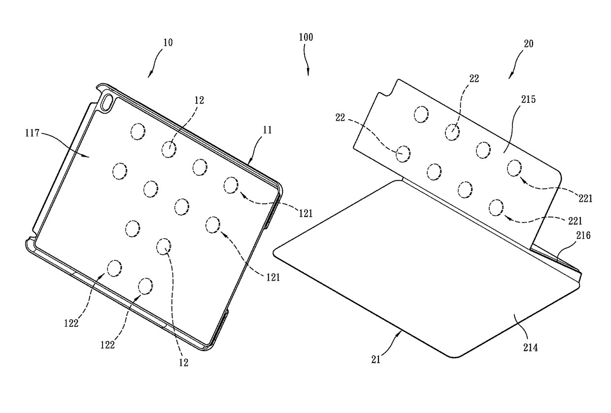
[0028]Referring to FIGS. 7-20, a first preferred embodiment of the present invention provides a protection enclosure of a portable electronic device, which is generally designated at 100, generally comprising a protective frame 10 and a protective cover 20.

[0029]Referring to FIGS. 7-9, the protective frame 10 comprises a protective frame main body 11 and a plurality of protective frame magnetic members 12. The protective frame main body 11 comprises a frame body 111, a frame body inner covering memb...


PUM


Abstract

A protection enclosure of an portable electronic device includes a protective frame including a protective frame main body in which the portable electronic device is received and held and multiple protective frame magnetic members, which are arranged in the protective frame main body at intervals and grouped as at least one lateral protective frame magnetic attraction row and at least one longitudinal protective frame magnetic attraction row perpendicular to the lateral protective frame magnetic attraction row; and a protective cover including a protective cover main body having a bottom board, an end board, and a connection board connected between the bottom board and the end board and multiple protective cover magnetic members arranged, at intervals, on the end board to form at least one protective cover magnetic attraction row. Foldability is available between the bottom board and the connection board and also between the connection board and the end board.

Description

(a) TECHNICAL FIELD OF THE INVENTION[0001]The present invention relates generally to an accessory of a portable electronic device, and more particularly to a protection enclosure of a portable electronic device.(b) DESCRIPTION OF THE PRIOR ART[0002]As shown in FIGS. 1 and 2, a conventional protection enclosure 1 comprises a protective frame 2 and a protective cover 3 pivotally connected together. The protective frame 2 may receive and hold a portable electronic device (such as a mobile phone and a tablet computer) therein. The protective cover 3 may be closed on and covers the portable electronic device or may be lifted open to allow the protective frame 2 to rotate so that the protective frame 2 and the portable electronic device can be positioned in an upright condition (as show in FIG. 1) or in a horizontal condition (as shown in FIG. 2) to allow for easy viewing by a user.[0003]However, for the know protection enclosure 1 discussed above, the angular positions of the protective ...

Claims


Application Information

Patent Timeline
IPC IPC(8): H04B1/3888G06F1/16H04M1/02
CPCH04B1/3888G06F1/1626H04M1/0202G06F2200/1633G06F1/1656H04M1/04A45C2011/002A45C2200/15A45C11/00A45C2011/003A45C13/1069
Inventor KUO, KUO-TANG
Owner KUO KUO TANG
Why Eureka
Try Eureka