
Cyclone separator for high gas volume fraction fluids

a technology of gas volume fraction and separator, which is applied in the direction of vortex flow apparatus, liquid degasification, separation process, etc., can solve the problems of large amount of oil discharged, relatively large volume of gas in the production fluid, etc., and achieve high heavy fraction/medium fraction separation efficiency

Active Publication Date: 2018-04-10
FMC SEPARATION SYST BV
View PDF16 Cites 0 Cited by
  • Summary
  • Abstract
  • Description
  • Claims
  • Application Information

AI Technical Summary

Benefits of technology

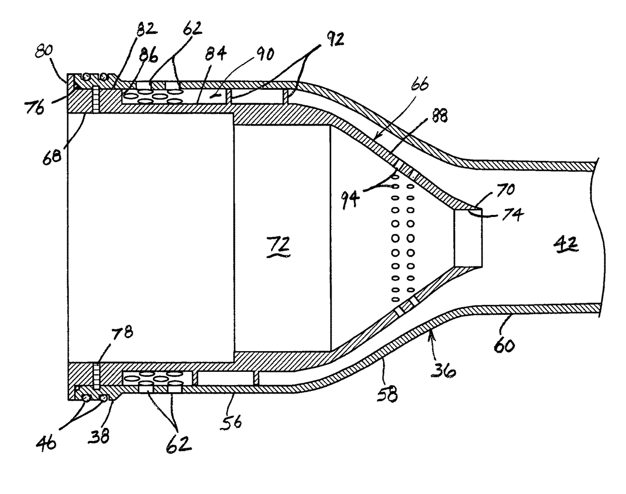
The present invention is a cyclone separator that can effectively separate heavy and medium fractions of fluid mixtures that contain a large volume of light fraction. The cyclone separator operates by first removing a significant amount of the light fraction to prevent it from interfering with the discharge of the medium fraction through the light fraction outlet. This results in high separation efficiency of the heavy fraction and medium fraction even when the light fraction is present in large volumes.

Problems solved by technology

Although these prior art cyclone separators work relatively well when the production fluid contains relatively small amounts of gas, problems arise when the volume of gas in the production fluid is relatively large.
This is due to the fact that the gas, being less dense than oil, is displaced toward the middle of the rotating production stream and consequently interferes with the discharge of the oil through the light fraction outlet.
As a result, larger amounts of oils than desired are discharged through the heavy fraction outlet with the water.

Method used


Image

  • Cyclone separator for high gas volume fraction fluids
  • Cyclone separator for high gas volume fraction fluids
  • Cyclone separator for high gas volume fraction fluids

Examples


Embodiment Construction

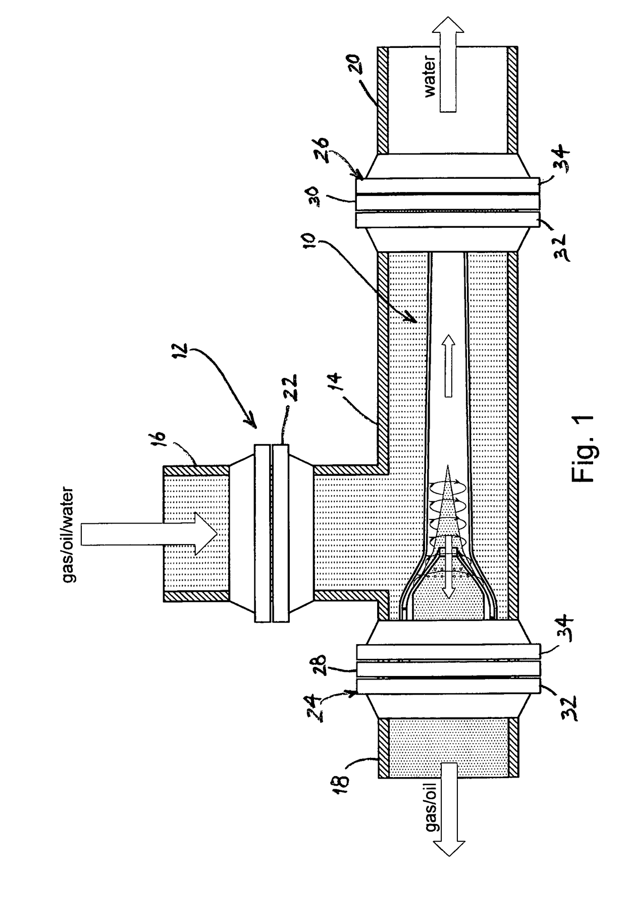
[0016]The present invention is directed to a cyclone separator for separating a multiphase fluid into its separate fractions. In the hydrocarbon production industry, for example, the multiphase fluid may comprise the production fluid from a hydrocarbon well. Depending on the well, the production fluid may comprise a heavy fraction such as water, a medium fraction such as oil and a light fraction such as gas. In such situations, a common objective is to separate the water from the oil and gas so that the water may be, e.g., re-injected into the well.

[0017]The cyclone separator of the present invention operates to first remove a substantial portion of the gas from the fluid stream and then separate the water from the oil. As a result, the cyclone separator can achieve relatively high oil / water separation efficiencies with fluid mixtures comprising relatively large volumes of the gas fraction. Although the invention is particularly useful for hydrocarbon production applications in whic...


PUM

PropertyMeasurementUnit
outer diameteraaaaaaaaaa
volumesaaaaaaaaaa
densityaaaaaaaaaa

Abstract

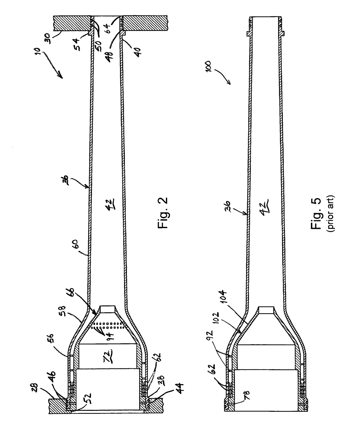
A cyclone separator for separating a heavy fraction from a multiphase fluid comprising a mixture of the heavy fraction, a medium fraction and a light fraction includes an elongated cyclone tube which comprises a fluid inlet, a heavy fraction outlet and a flow bore that extends between the fluid inlet and the heavy fraction outlet. A mandrel is positioned concentrically within the cyclone tube and comprises a light fraction outlet that extends generally axially therethrough and an outer diameter surface that together with the cyclone tube defines an annular flow path for the multiphase fluid which extends between the fluid inlet and the flow bore. The outer diameter surface comprises a generally cylindrical section which extends from proximate the fluid inlet to a convergence section which extends toward an outlet port that connects the light fraction outlet with the flow bore, and the mandrel further comprises a plurality of outlet holes which extend through the convergence section between the flow path and the light fraction outlet.

Description

BACKGROUND OF THE INVENTION[0001]The present invention relates to a cyclone separator for separating a multiphase fluid into its different fractions. In particular, the invention relates to a cyclone separator which is effective for separating a multiphase fluid comprising heavy, medium and light fractions into a heavy fraction and a mixture of light and medium fractions. In this manner, comparatively high heavy fraction / light fraction separation efficiencies may be achieved even when the fluid contains relatively large volumes of the light fraction.[0002]Bulk de-oilers and hydrocyclones, which may be referred to generically as cyclone separators, are used in the hydrocarbon production industry to separate multiphase fluid streams into their different fractions so that these fractions may be treated separately. For example, cyclone separators are commonly used to separate the production fluid from a hydrocarbon well into separate streams of oil and water so that the oil can be conve...

Claims


Application Information

Patent Timeline
Patent Type & Authority Patents(United States)
IPC IPC(8): B04C5/13B01D17/02B01D19/00
CPCB04C5/13B01D19/0057B01D17/0217
Inventor AKDIM, MOHAMED REDAABDALLA, TARIG MUKTHAR
Owner FMC SEPARATION SYST BV
Learn More