
Air conditioning device for vehicle

a technology for air conditioning devices and vehicles, applied in vehicle heating/cooling devices, vehicle components, transportation and packaging, etc., can solve problems such as possible fluctuation

Active Publication Date: 2018-04-10
DENSO CORP
View PDF19 Cites 0 Cited by
  • Summary
  • Abstract
  • Description
  • Claims
  • Application Information

AI Technical Summary

Benefits of technology

[0008]It is an objective of the present disclosure to provide an air conditioning device for vehicle capable of restricting air that has flowed out from a cooling heat exchanger from flowing around to a downstream wall surface of a heating heat exchanger.
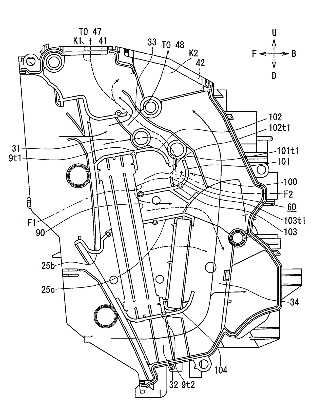
[0015]In order to restrict the contact heating air, the guide plates have the third guide that extends from the first guide toward the end of the second guide. Consequently, the generation of the contact heating air is restricted and hence a fluctuation of a temperature of air conditioning air can be restricted.
[0018]In the air conditioning device for vehicle, a relation of the dimension A and the dimension B as to which is larger than which may be expressed as: B≤A. The dimension A and the dimension B regulate dimensions of inlet and outlet ports of a flow of air. Outgoing air is air that passes along the first path K1. Meanwhile, incoming air is air that flows in from a space between the end of the first guide and the end of the second guide. The inflow air turns to the contact heating air that is heated upon contact with the downstream wall surface of the heating heat exchanger. When the dimension A is smaller than the dimension B (A<B), ventilation resistance is generated against a flow of air passing along the first path. Hence, an air volume is reduced and a preferable air volume ratio cannot be obtained. Moreover, blown air noise may become louder. However, by setting the relation of the dimension A and the dimension B as to which is larger than which to be expressed as: B≤A, a reduction in air volume and blown air noise can be restricted.

Problems solved by technology

Such heating may possibly give rise to a fluctuation of a temperature of air conditioning air blown into the vehicle compartment.

Method used


Image

  • Air conditioning device for vehicle
  • Air conditioning device for vehicle
  • Air conditioning device for vehicle

Examples


first embodiment

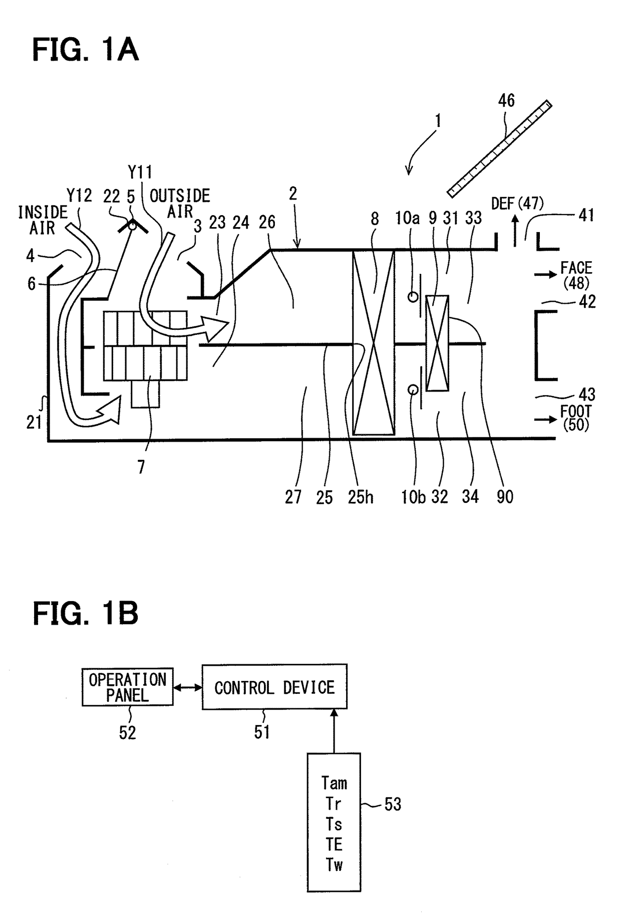
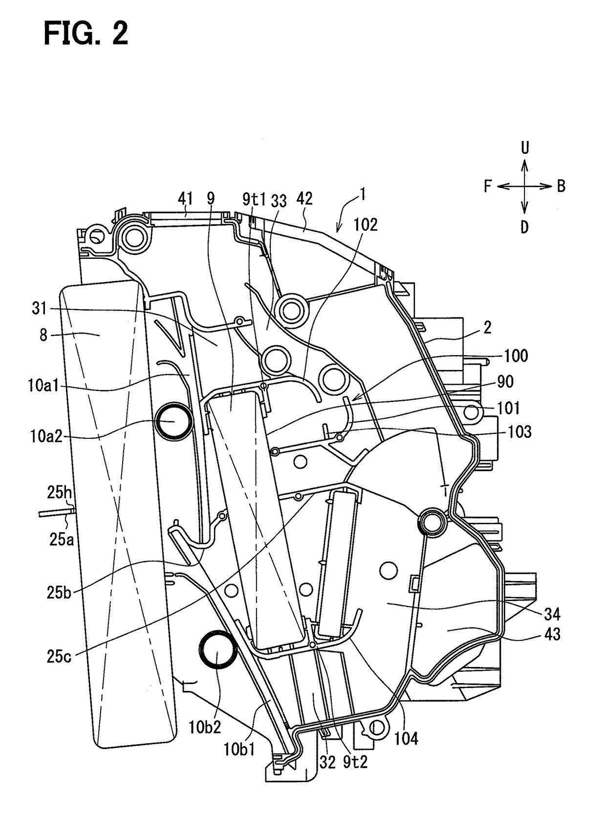
[0030]Hereinafter, a first embodiment of the present disclosure will be described in detail using FIG. 1A through FIG. 5. FIG. 1A schematically shows an air conditioning device 1 for vehicle for vehicle according to the first embodiment of the present disclosure. FIG. 2 shows a part of an air conditioning unit of the air conditioning device for vehicle of the first embodiment. In FIG. 2, arrows pointing upward, downward, forward, and backward denote, respectively, an upward direction U (vehicle ceiling direction), a downward direction D (vehicle floor direction), a forward direction F (vehicle forward movement direction), and a backward direction B (vehicle backward movement direction) when the air conditioning unit is equipped to a vehicle. The first embodiment describes the air conditioning device 1 for vehicle for vehicle adopting an inside and outside air bi-level structure, by which inside air and outside air can be sent through separate air passages.

[0031]Referring to FIG. 1A,...

second embodiment

[0121]A second embodiment will now be described. In respective embodiments below, a description of components same as the counterparts of the first embodiment above is omitted by attaching same reference numerals and a description will be given to a different configuration. In the second and subsequent embodiments, reference numerals same as the reference numerals used in the first embodiment above denote the same configurations and the description given above is also applied herein.

[0122]FIG. 6 shows the second embodiment of the present disclosure. Referring to FIG. 6, an electric heater as a heating sub-heat exchanger 9x forming another exchanger is provided downstream of a heating heat exchanger 9 forming a heater core. The electric heater is capable of controlling an amount of heat generation by switching connections of multiple PTC heaters.

[0123]An upper end of the heating sub-heat exchanger 9x forming a heat exchanger other than a cooling heat exchanger 8 and the heating heat ...

third embodiment

[0124]A third embodiment of the present disclosure will now be described. A description will be given to a portion different from the embodiments described above. FIG. 7 shows the third embodiment of the present disclosure. Referring to FIG. 7, an air conditioning device for vehicle has a partition plate 25 (25a through 25c) that forms an inside and outside air bi-level structure.

[0125]A heating sub-heat exchanger 9x2 forming a heat exchanger other than a cooling heat exchanger 8 and a heating heat exchanger 9 is provided below the partition plate 25. An upper end of the heating sub-heat exchangers 9x2 is held on the partition plate 25c and a lower end is held on a lower end guide 104 that bends in an upward direction U. The heating sub-heat exchanger 9x2 is formed of an electric heater or a condenser that forms a heat pump cycle.

[0126]While the embodiments above have been described as preferred embodiments of the present disclosure, the present disclosure is not limited to the embo...


PUM


Abstract

An air conditioning device for vehicle has guide plates that guide a flow of air on a downstream side of a heating heat exchanger. In order to form a first path, the guide plates have a first guide that extends from a downstream wall surface of the heating heat exchanger and bends in an upward direction. Further, in order to hold a heat exchanger other than a cooling heat exchanger and the heating heat exchanger, the guide plates have a second guide that extends from an upper end part of the heating heat exchanger and bends in a downward direction. Furthermore, the guide plates have a third guide that extends from the first guide toward an end of the second guide.

Description

CROSS REFERENCE TO RELATED APPLICATIONS[0001]This application is a U.S. National Phase Application under 35 U.S.C. 371 of International Application No. PCT / JP2014 / 002918 filed on Jun. 3, 2014 and published in Japanese as WO 2014 / 199588 A1 on Dec. 18, 2014. This application is based on and claims the benefit of priority from Japanese Patent Application No. 2013-125965 filed on Jun. 14, 2013. The entire disclosures of all of the above applications are incorporated herein by reference.TECHNICAL FIELD[0002]The present disclosure relates to an air conditioning device for vehicle, provided with a heating heat exchanger that is installed inside an air conditioning case and heats cold air from an evaporator. More particularly, the present disclosure relates to an air conditioning device for vehicle that restricts unintended heating of the cold air by a downstream wall surface of the heating heat exchanger when the cold air flows above the heating heat exchanger with bypassing the heating he...

Claims


Application Information

Patent Timeline
Patent Type & Authority Patents(United States)
IPC IPC(8): B60H1/00B60H1/22
CPCB60H1/00035B60H1/00064B60H1/2215B60H1/00564B60H2001/00092
Inventor SAKAKIBARA, DAISUKE
Owner DENSO CORP
Learn More