Antenna, circular polarized patch antenna, and vehicle having the same
a patch antenna and circular polarization technology, applied in the field of antennas, can solve the problems of increasing the overall size of the integrated antenna and the increase of the cost of the product, so as to reduce the size (volume) of the antenna, prevent the performance degradation of the antenna, and reduce the cost of the antenna
- Summary
- Abstract
- Description
- Claims
- Application Information
AI Technical Summary
Benefits of technology
Problems solved by technology
Method used
Image
Examples
first exemplary embodiment
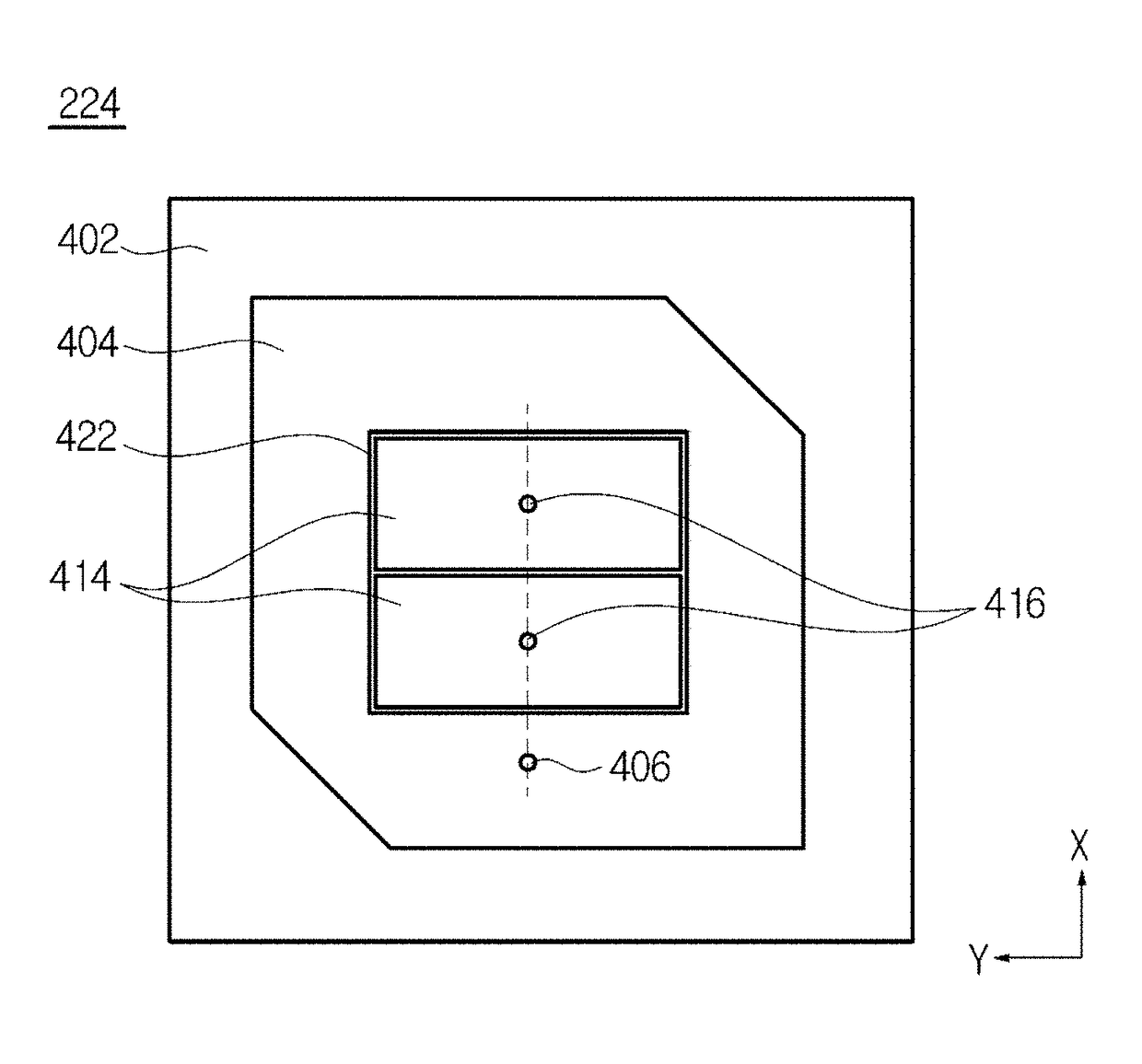
[0038]FIGS. 4A and 4B are exemplary views showing a circular polarized patch antenna in accordance with a first exemplary embodiment of the present invention. FIG. 4A is an exemplary perspective view of a plane of the circular polarized patch antenna 224, and FIG. 4B is an exemplary plan view of the circular polarized patch antenna 224. As shown in FIGS. 4A and 4B, in the circular polarized patch antenna 224 in accordance with the first exemplary embodiment of the present invention, a positive (+1) mode radiator 404 (first radiator) and a plurality of negative (−1) mode radiators 414 (second radiator) may be formed on a plane of a substrate 402.
[0039]The substrate 402 may be a printed circuit board (PCB) made of a dielectric material (for example, FR4). The substrate 402 may be formed to have a thickness of approximately 5 mm. An area of the substrate 402 is an area in which the positive (+1) mode radiator 404 and the negative (−1) mode radiator 414 may be received on a surface of a...
second exemplary embodiment
[0055]FIGS. 11A and 11B are exemplary views showing a circular polarized patch antenna in accordance with a second exemplary embodiment of the present invention. A circular polarized patch antenna 11224 according to a second exemplary embodiment of the present invention is an exemplary embodiment in which a feeding probe 1106 may be disposed in a position deviated from a substantially straight line to virtually connect a plurality of vias 1116.
[0056]As shown in FIG. 11A, the feeding probe 1106 may be disposed in a position apart by a distance d1 to the left side on the substantially straight line to virtually connect the plurality of vias 1116, and therefore characteristics of direct power feeding of a positive (+1) mode radiator 1104 and coupling power feeding of a negative (−1) mode radiator 1114 may be changed. In addition, as shown in FIG. 11B, the feeding probe 1106 may be disposed in a position apart by a distance d2 to the right side on the straight line to virtually connect ...
third exemplary embodiment
[0057]FIG. 12 is an exemplary view showing a circular polarized patch antenna in accordance with a third exemplary embodiment of the present invention. In a circular polarized patch antenna 12224 according to a third exemplary embodiment of the present invention shown in FIG. 12, a negative (−1) mode radiator 1214 may include a plurality of rectangular patches divided into a quadrant. In particular, vias 1216 may be disposed in each of the plurality of rectangular patches of the circular polarized patch antenna 12224 according to the third exemplary embodiment of the present invention. In the circular polarized patch antenna 12224 according to the third exemplary embodiment of the present invention, a feeding probe 1206 may be disposed on a positive (+1) mode radiator 1204 with a first end of the feeding probe 1206 in direct contact with the positive (+1) mode radiator 1204 and in indirect contact with the negative (−1) mode radiator 1214. Accordingly, power may be fed directly to t...
PUM
 Abstract
Description
Claims
Application Information
 - R&D
- Intellectual Property
- Life Sciences
- Materials
- Tech Scout
- Unparalleled Data Quality
- Higher Quality Content
- 60% Fewer Hallucinations
Browse by: Latest US Patents, China's latest patents, Technical Efficacy Thesaurus, Application Domain, Technology Topic, Popular Technical Reports.
© 2025 PatSnap. All rights reserved.Legal|Privacy policy|Modern Slavery Act Transparency Statement|Sitemap|About US| Contact US: help@patsnap.com


