Antenna, circular polarized patch antenna, and vehicle having the same

a patch antenna and circular polarized technology, applied in the direction of resonant antennas, substantially flat resonant elements, radiating element structural forms, etc., can solve the problems of increasing the overall size of the integrated antenna and the increase in the cost of the product, so as to reduce the size (volume) of the antenna, prevent the performance degradation of the antenna, and reduce the cost of the antenna

Active Publication Date: 2016-04-28
HYUNDAI MOTOR CO LTD
View PDF4 Cites 9 Cited by
  • Summary
  • Abstract
  • Description
  • Claims
  • Application Information

AI Technical Summary

Benefits of technology

[0006]Therefore, an aspect of the present invention provides an antenna which may reduce the size (volume) of the antenna. In addition, the present invention provides an antenna which may reduce the cost of the antenna. Further, the present invention provides an antenna which may prevent performance degradation of the antenna and improve isolation. Additional aspects of the invention will be set forth in part in the description which follows and, in part, will be obvious from the description, or may be learned by practice of the invention.

Problems solved by technology

In addition, to prevent the performance degradation between the two patch antennas and improve isolation, an interval between antenna elements should be spaced sufficiently apart from each other which may cause an increase in the overall size of the integrated antenna and an increase in the cost of the product.

Method used


Image

  • Antenna, circular polarized patch antenna, and vehicle having the same
  • Antenna, circular polarized patch antenna, and vehicle having the same
  • Antenna, circular polarized patch antenna, and vehicle having the same

Examples


first exemplary embodiment

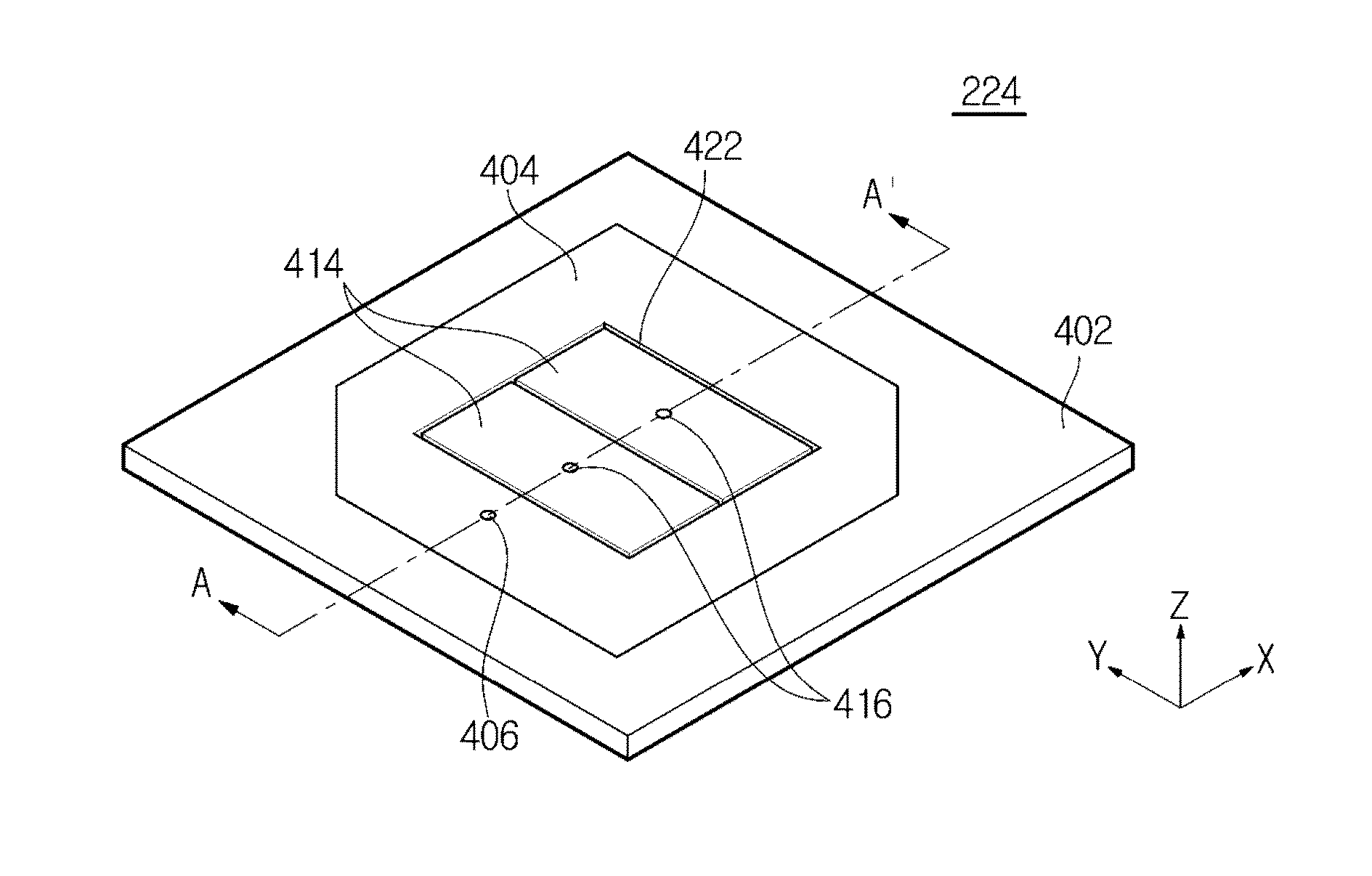
[0038]FIGS. 4A and 4B are exemplary views showing a circular polarized patch antenna in accordance with a first exemplary embodiment of the present invention. FIG. 4A is an exemplary perspective view of a plane of the circular polarized patch antenna 224, and FIG. 4B is an exemplary plan view of the circular polarized patch antenna 224. As shown in FIGS. 4A and 4B, in the circular polarized patch antenna 224 in accordance with the first exemplary embodiment of the present invention, a positive (+1) mode radiator 404 (first radiator) and a plurality of negative (−1) mode radiators 414 (second radiator) may be formed on a plane of a substrate 402.

[0039]The substrate 402 may be a printed circuit board (PCB) made of a dielectric material (for example, FR4). The substrate 402 may be formed to have a thickness of approximately 5 mm. An area of the substrate 402 is an area in which the positive (+1) mode radiator 404 and the negative (−1) mode radiator 414 may be received on a surface of a...

second exemplary embodiment

[0055]FIGS. 11A and 11B are exemplary views showing a circular polarized patch antenna in accordance with a second exemplary embodiment of the present invention. A circular polarized patch antenna 11224 according to a second exemplary embodiment of the present invention is an exemplary embodiment in which a feeding probe 1106 may be disposed in a position deviated from a substantially straight line to virtually connect a plurality of vias 1116.

[0056]As shown in FIG. 11A, the feeding probe 1106 may be disposed in a position apart by a distance d1 to the left side on the substantially straight line to virtually connect the plurality of vias 1116, and therefore characteristics of direct power feeding of a positive (+1) mode radiator 1104 and coupling power feeding of a negative (−1) mode radiator 1114 may be changed. In addition, as shown in FIG. 11B, the feeding probe 1106 may be disposed in a position apart by a distance d2 to the right side on the straight line to virtually connect ...

third exemplary embodiment

[0057]FIG. 12 is an exemplary view showing a circular polarized patch antenna in accordance with a third exemplary embodiment of the present invention. In a circular polarized patch antenna 12224 according to a third exemplary embodiment of the present invention shown in FIG. 12, a negative (−1) mode radiator 1214 may include a plurality of rectangular patches divided into a quadrant. In particular, vias 1216 may be disposed in each of the plurality of rectangular patches of the circular polarized patch antenna 12224 according to the third exemplary embodiment of the present invention. In the circular polarized patch antenna 12224 according to the third exemplary embodiment of the present invention, a feeding probe 1206 may be disposed on a positive (+1) mode radiator 1204 with a first end of the feeding probe 1206 in direct contact with the positive (+1) mode radiator 1204 and in indirect contact with the negative (−1) mode radiator 1214. Accordingly, power may be fed directly to t...


PUM


Abstract

An antenna, a circular polarized patch antenna, and a vehicle having the same are provided. The antenna includes a substrate, a ground portion formed on a first surface of the substrate, and a second radiator having a plurality of patches and formed on a second surface of the substrate. In addition, a first radiator is formed in a periphery of the second radiator with a gap from the second radiator and a feeding probe is disposed on the first radiator to enable power to be fed directly fed to the first radiator and to enable power to be fed to the second radiator through coupling.

Description

CROSS-REFERENCE TO RELATED APPLICATION[0001]This application claims the benefit of Korean Patent Application No. P2014-143926, filed on Oct. 23, 2014 in the Korean Intellectual Property Office, the disclosure of which is incorporated herein by reference.BACKGROUND[0002]1. Field[0003]The present invention relates to an antenna, and more particularly, to a circular polarized patch antenna.[0004]2. Description of the Related Art[0005]An integrated antenna for vehicles generally includes a global positioning system (GPS) function and a reception function of satellite digital audio radio service (SDARS). To implement the respective functions, a patch antenna that satisfies each of a GPS band and an SDARS band is used, but in this case, two patch antennas are required. In addition, to prevent the performance degradation between the two patch antennas and improve isolation, an interval between antenna elements should be spaced sufficiently apart from each other which may cause an increase ...

Claims


Application Information

Patent Timeline
Patent Type & Authority Applications(United States)
IPC IPC(8): H01Q9/04H01Q1/32
CPCH01Q9/0407H01Q1/3208H01Q9/045H01Q1/3275H01Q9/0428H01Q15/0086H01Q1/32H01Q1/38
Inventor KIM, DONGJINKIM, IN HO
Owner HYUNDAI MOTOR CO LTD
Why Eureka
Try Eureka