
Heat exchanger for phase-changing refrigerant, with horizontal distributing and collecting tube

a heat exchanger and refrigerant technology, applied in the direction of tubular elements, stationary conduit assemblies, steam/vapor condensers, etc., can solve the problems of increasing the difficulty of using horizontal heat exchangers and increasing the cos

Active Publication Date: 2018-04-17
THERMOFIN
View PDF26 Cites 0 Cited by
  • Summary
  • Abstract
  • Description
  • Claims
  • Application Information

AI Technical Summary

Benefits of technology

The invention is a heat exchanger that can efficiently distribute refrigerant gas or liquid and separate them from oil before heat transfer in the tubes, while also allowing for phase separation of the coolant after heat transfer. This design reduces installation space and cost.

Problems solved by technology

It is a disadvantage of the recited embodiment that effective oil separation and an effective coolant collector function have to be taken over by additional components which makes using horizontal heat exchangers more difficult and more expensive.

Method used


Image

  • Heat exchanger for phase-changing refrigerant, with horizontal distributing and collecting tube
  • Heat exchanger for phase-changing refrigerant, with horizontal distributing and collecting tube
  • Heat exchanger for phase-changing refrigerant, with horizontal distributing and collecting tube

Examples


Embodiment Construction

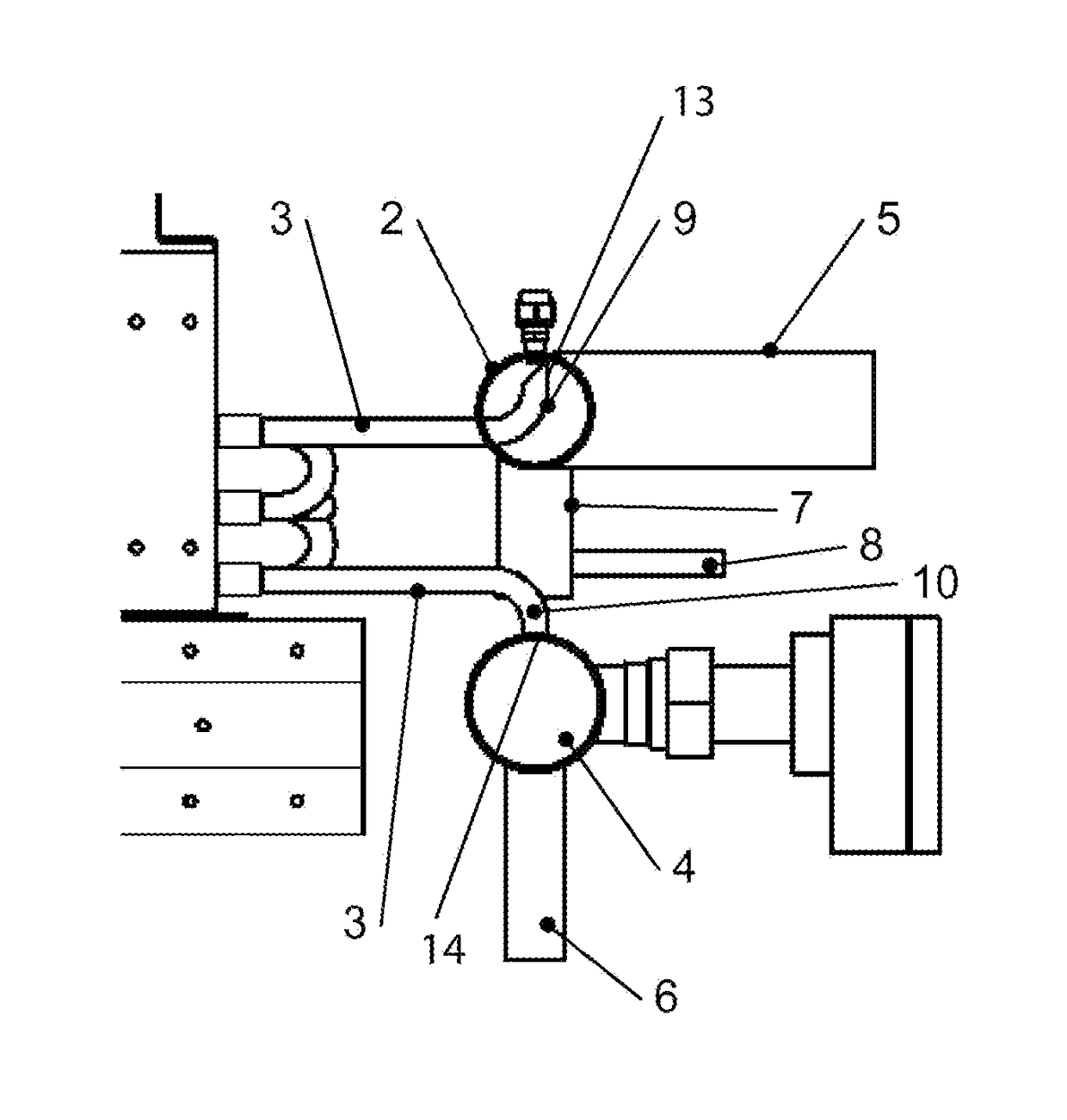
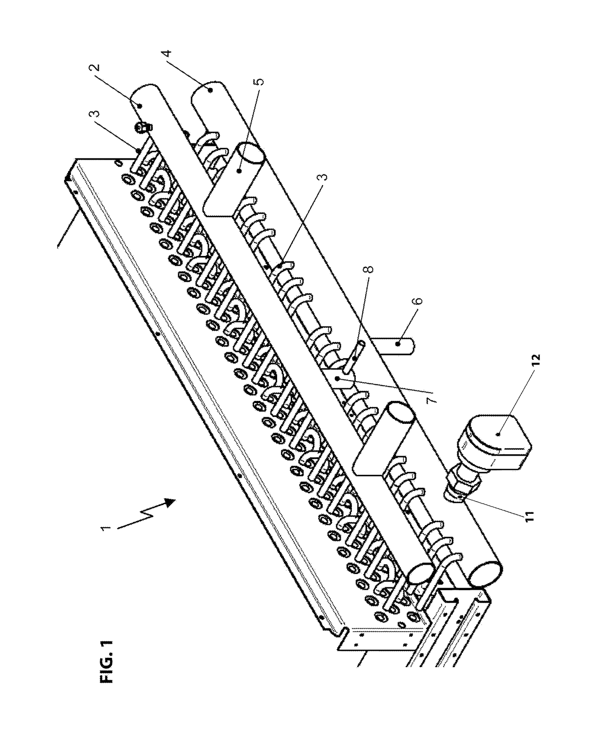
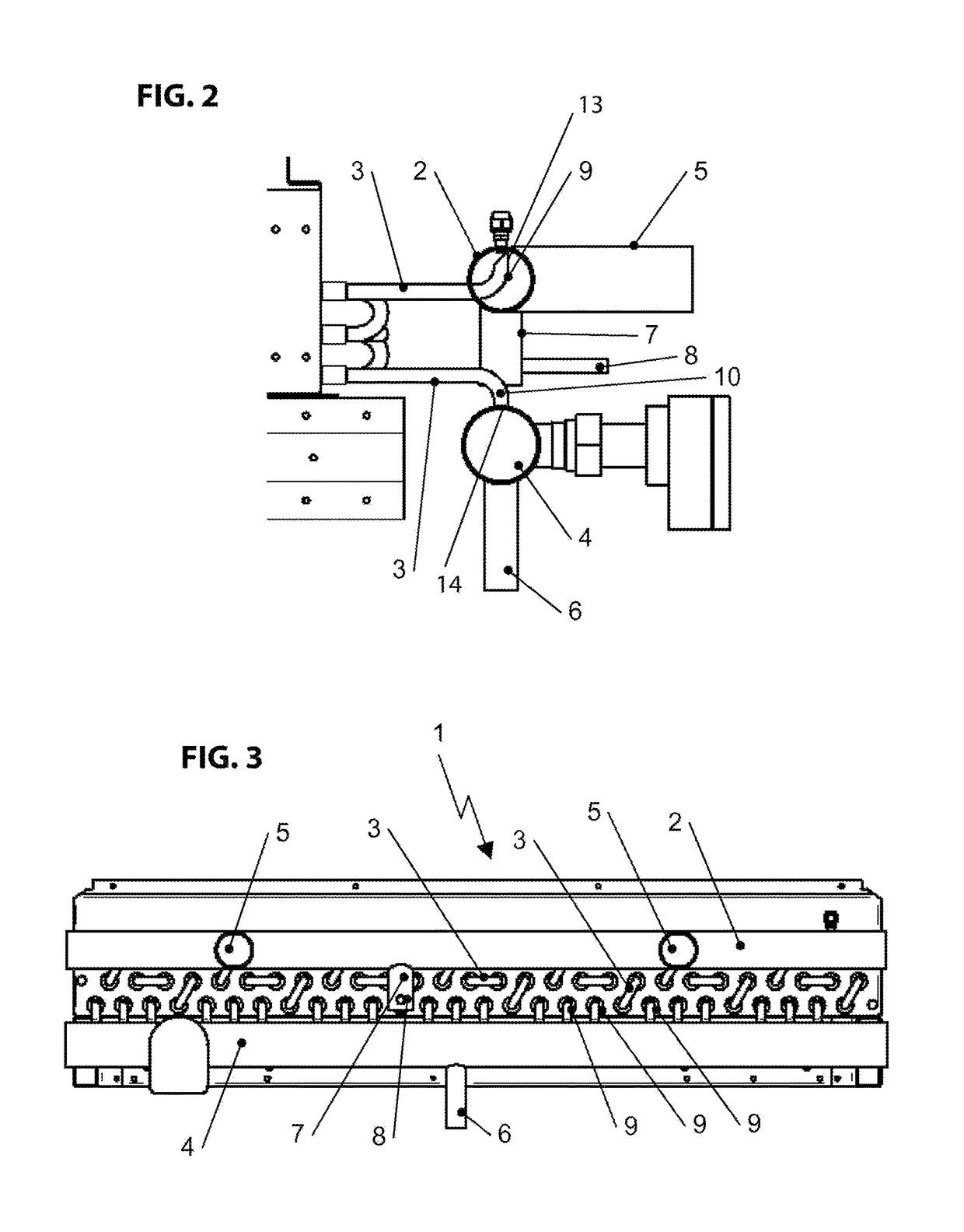
[0025]FIG. 1 illustrates a heat exchanger 1 in a horizontal flat lying embodiment. A flat lying embodiment of the heat exchanger 1 means that the heat exchanger tubes 3 are connected horizontally in a plane with several channels at the horizontal distributor 2. Thus, the number of channels of the heat exchanger results from the number of heat exchanger tubes 3 exiting from the distributor tube 2. The heat exchanger tubes 3 run through the heat exchanger 1 in several planes in downward direction and are introduced in the lowest plane into the collector tube 4. The distributor tube 2 includes two gas- and oil inlet spouts 5 through which the refrigerant vapor-oil mix flows through the gas- and oil inlet spouts 5 into the distributor tube 2. In the distributor tube 2 the gas- and oil droplet mix is distributed horizontally, wherein a separation within the cross section of the distributor tube 2 is provided so that the refrigerant vapor deposits in the upper portion of the cross section...


PUM


Abstract

An exchanger for a phase changing refrigerant including a horizontal distributor tube, a horizontal collector tube, and at least one refrigerant carrying heat exchanger tube connected therebetween. A refrigerant gas inlet into the at least one heat exchanger tube is arranged in an upper portion of a cross section of the horizontal distributor tube. A refrigerant outlet from the at least one heat exchanger tube is arranged in an upper portion of a cross section of the horizontal collector tube for condenser operation of the multi channel heat exchanger so that oil separation is provided in a lower portion of the cross section of the horizontal distributor tube and liquid refrigerant separation is provided in a lower portion of the cross section of the horizontal collector tube.

Description

RELATED APPLICATIONS[0001]This application is a continuation of PCT / EP2011 / 058421, filed on May 24, 2011, claiming priority from European Patent Application EP 101 649 93.7, filed on Jun. 4, 2010, both of which are incorporated in their entirety by this reference.FIELD OF THE INVENTION[0002]The invention relates to a multi channel heat exchanger for a refrigerant cycle. Heat exchangers of this type are used for example as condensers or evaporators in cooling- or heat pump cycles with a phase changing refrigerant.BACKGROUND OF THE INVENTION[0003]Multi channel heat exchangers essentially include a distributor which distributes the refrigerant over plural heat exchanger pipes, plural heat exchanger pipes in which the refrigerant is brought into indirect contact with the medium to be cooled or heated and a collector in which the refrigerant is collected from the plural heat exchanger pipes that are typically run in parallel before the refrigerant eventually leaves the heat exchanger.[00...

Claims


Application Information

Patent Timeline
Patent Type & Authority Patents(United States)
IPC IPC(8): F25B43/02F25B39/00F28B1/06F28F1/00F28B9/08F28B9/02F25B43/00F25B39/02F28D1/053F28D1/047
CPCF25B43/02F25B39/00F28B1/06F28B9/02F28B9/08F28F1/00F28D1/05341F25B43/006F25B2400/02F25B2400/03F25B2400/23F28D1/0477F25B39/028
Inventor KOCH, KLAUS
Owner THERMOFIN
Learn More