
Actuator

a technology of actuators and actuators, applied in the field of actuators, can solve the problem of low overall installation space requirements of actuators, and achieve the effect of low loss of magnetic flux and high degree of magnetostriction

Active Publication Date: 2017-06-27
ROBERT BOSCH GMBH
View PDF16 Cites 0 Cited by
  • Summary
  • Abstract
  • Description
  • Claims
  • Application Information

AI Technical Summary

Benefits of technology

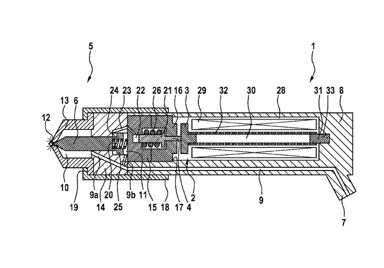
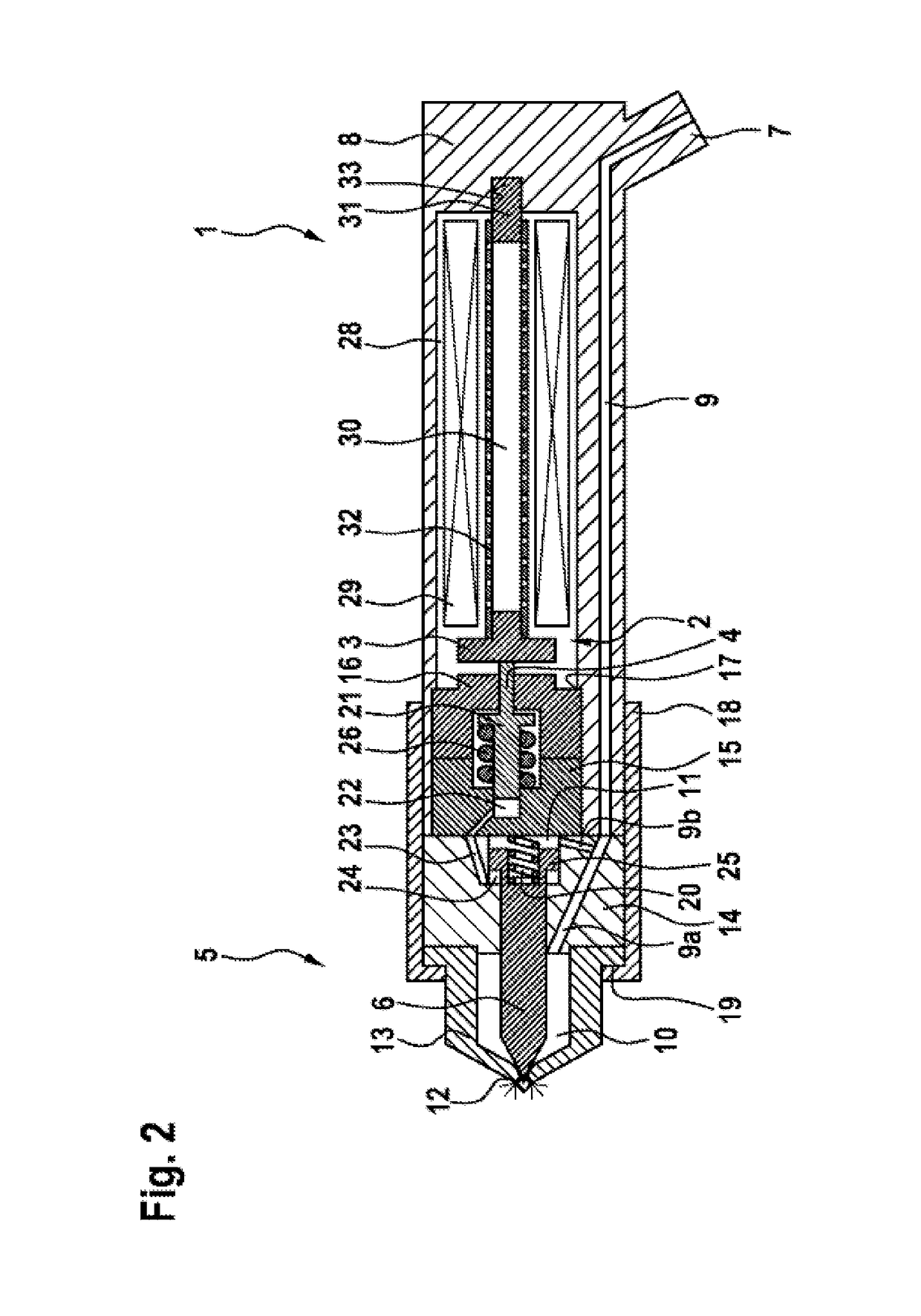
[0004]This object is achieved in that the actuator is additionally designed as a solenoid. The method according to the invention is distinguished in that, when current is applied to the coil, a magnetic flux forms across the armature, the tappet, a sliding piece and the housing, the magnetostrictive tappet being extended by said magnetic flux, and, after a limit extension is reached, the attraction force between the armature plate and the armature counterpiece is large enough to move the armature, together with the tappet and the sliding piece, to bear against the armature counterpiece. In this case, the actuator additionally acts as a solenoid. The particular advantage of the invention therefore lies in the combination of a magnetostrictive actuator or magnetostrictively acting actuator with a solenoid, wherein the two actuator concepts share a magnetic circuit. Several advantages are achieved as a result. Only one coil is required, as a result of which the installation space requirement for the actuator is low overall. The number of components is likewise low. The magnetostrictive actuator has to cover only a small actuating travel distance, and therefore said magnetostrictive actuator can be of small design overall. Finally, the force profile of the actuator combination which is designed in this way can be better matched to corresponding requirements. Therefore, in summary, an actuator is provided which is able to realize large actuating travel distances at high actuating forces together with a clear structure and low costs.
[0005]In one development of the invention, the tappet is of magnetostrictive design. Magnetostriction is the deformation of magnetic (in particular ferromagnetic) substances as a result of a magnetic field being applied. In the process, the body, in the present case the tappet, experiences an elastic change in length at a constant volume. Suitable materials for the tappet include materials with a high degree of magnetostriction, for example Terfenol or iron / nickel alloys.
[0006]In a further refinement of the invention, the tappet is arranged between the armature and, on the opposite side, a sliding piece. When current is applied to the coil, the tappet extends and displaces the armature ultimately as far as a limit extension amount in relation to the sliding piece which is supported in a manner fixed to the housing.
[0007]In one development of the invention, the armature and the sliding piece are connected to one another by means of a spring which surrounds the tappet. The spring applies the necessary pretension to the tappet. In a further refinement, the spring is in this case designed as a sleeve spring which is additionally a tension spring. The sleeve spring is fixedly connected to the armature and to the sliding piece and clamps the tappet between said components with a defined force.
[0008]In one development of the invention, the sliding piece is of cylindrical design and is guided in a recess in the housing. Firstly, this results in the assembly, comprising the sliding piece, the tappet, the armature and the sleeve spring, being guided, and secondly, a low-loss magnetic flux is ensured by the guidance.
[0009]In one development of the invention, the coil is arranged in the housing so as to surround at least the tappet and the spring. In the process, the coil can further also surround a subregion in each case of the armature and of the sliding piece in order to exert a force, which is as constant as possible, on the components even during the intended movements of the components.

Problems solved by technology

Only one coil is required, as a result of which the installation space requirement for the actuator is low overall.

Method used


Image

  • Actuator
  • Actuator
  • Actuator

Examples


Embodiment Construction

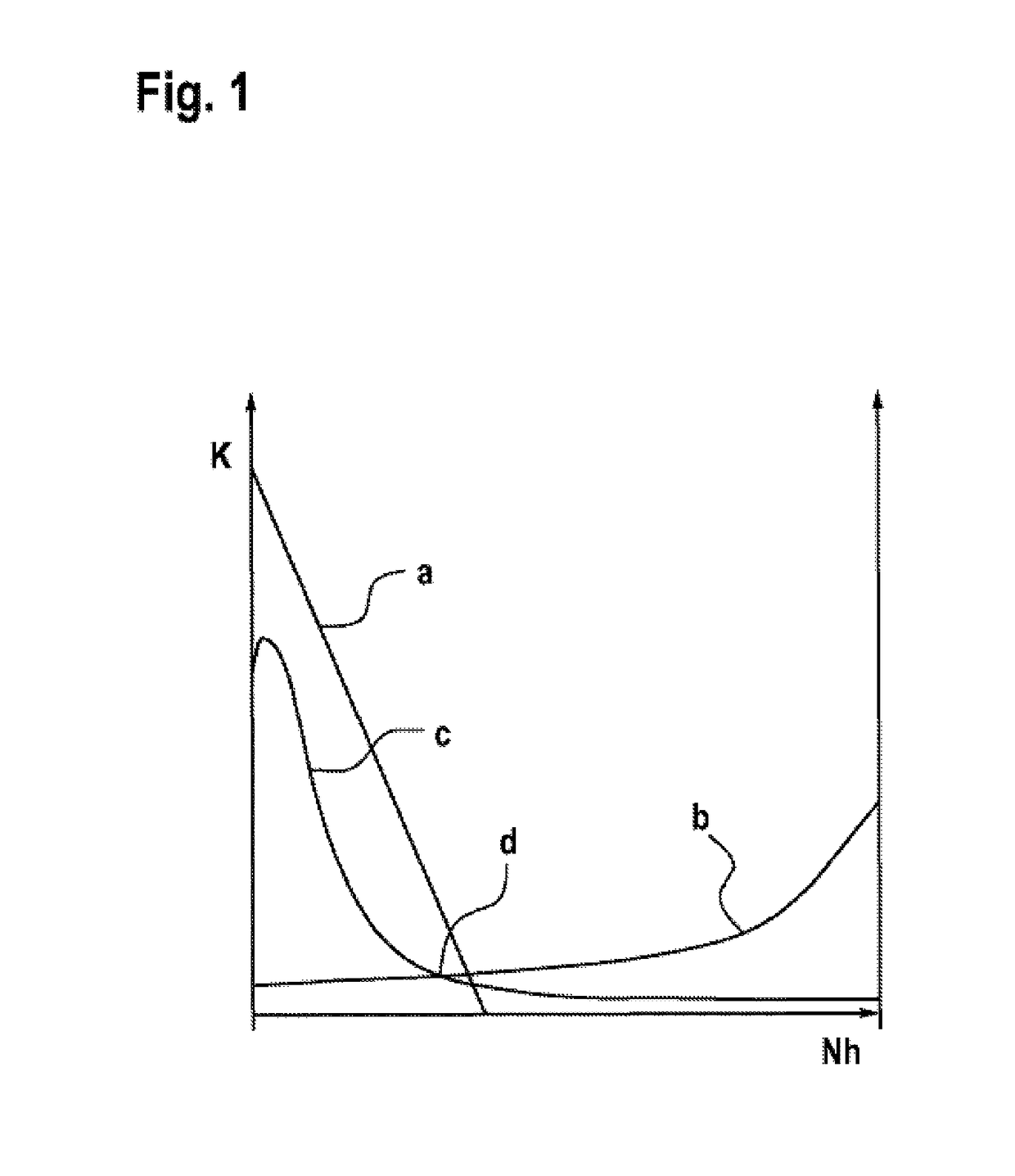
[0015]FIG. 1 shows a force / distance graph with various force profiles or stroke profiles of different actuators and a typical hydraulic force profile which has to be exerted on a valve needle of a fuel injector in order to move said valve needle.

[0016]In the graph, the needle stroke Nh (or actuating travel distance) of a valve needle, which needle stroke corresponds to an air gap, which is to be overcome, in a (magnetic) actuator, is plotted on the abscissa, and the force K is plotted on the ordinate. The characteristic curve a indicates the typical force profile of a magnetostrictive actuator which, starting from a high initial force and a then linearly decreasing force, covers only a small overall actuating travel distance. The characteristic curve b indicates the typical force profile of a magnetic lifting actuator (solenoid) which, starting from a low initial force, exhibits an increasing increase in force with a large overall actuating travel distance. The characteristic curve ...


PUM

PropertyMeasurementUnit
magnetostrictiveaaaaaaaaaa
magnetic fluxaaaaaaaaaa
actuating forcesaaaaaaaaaa

Abstract

The invention relates to an actuator (1) comprising a housing (8), a coil (29) and an armature (2) which interacts with a tappet (30) and a spring, the armature plate (3) thereof being arranged to lie opposite an armature counterpiece (16), and said actuator (1) comprising at least one magnetostrictively-active component. According to the invention, an actuator (1) is provided with which large actuating paths can be travelled at high actuating forces. This is achieved by the actuator (1) additionally being designed to act as a solenoid.

Description

BACKGROUND OF THE INVENTION[0001]The invention relates to an actuator, having a housing, a coil, an armature which interacts with a tappet and a spring, and of which the armature plate is arranged opposite an armature counterpiece, and wherein the actuator has at least one magnetostrictively acting component. The invention further relates to a method for operating an actuator of this kind.[0002]An actuator of this kind is known from DE 198 43 534 A1. This actuator is installed on a fuel injector for an internal combustion engine. In this case, the magnetostrictive actuator is screwed to the side of the fuel injector and, by means of a hydraulic fluid, transmits a movement which is executed by the actuator to the valve needle of the fuel injector. To this end, a transmitter plunger is additionally arranged between the actuator and the space which accommodates the hydraulic liquid. Overall, the actuator, which is formed in this way and has the fuel injection valve, is of complicated c...

Claims


Application Information

Patent Timeline
Patent Type & Authority Patents(United States)
IPC IPC(8): F02M63/00H01F7/16H01L41/06H02N2/02H01L41/12F02M51/06
CPCF02M51/061F02M51/0603F02M51/0635F02M63/0063F02M63/0066H01F7/1607H01L41/06H01L41/12H02N2/02F02M2200/50F02M2200/704H10N35/80H10N35/00
Inventor BEIER, MARCORETTICH, ANDREASPAUER, THOMASRICCO, MARIO
Owner ROBERT BOSCH GMBH
Learn More