
Electromagnetic actuator arrangement

a technology of actuator arrangement and actuator, which is applied in the direction of machines/engines, magnetic bodies, instruments, etc., can solve the problems of inability to distinguish which of the armatures is extended, the axial position of the shift gate is not directly determinable, and the integrated sensor cannot detect whether an armature is retracted or extended, etc., to achieve the effect of low installation space and little installation spa

Pending Publication Date: 2022-05-12
ETO MAGNETIC GMBH
View PDF0 Cites 0 Cited by
  • Summary
  • Abstract
  • Description
  • Claims
  • Application Information

AI Technical Summary

Benefits of technology

This patent describes an electromagnetic actuator device that uses magnetic field and electric field detection means to detect the position of a shift gate. The detection means can be integrated into the housing of the actuator device, making it more compact and easier to install. The actuator arrangement can also include a magnetic field shield to protect the detection field from interference. The device can have multiple actuator units that can independently apply force to multiple plunger units. These technical effects provide a more efficient and cost-effective solution for detecting the position of a shift gate.

Problems solved by technology

The disadvantage of such a lift detection on the armature is that the axial position of the shift gate is not directly determinable.
Another disadvantage of the lift detection on the armature is that the integrated sensor can only detect whether an armature is retracted or extended.
However, in a sliding cam actuator which has several actuators, it is not possible to distinguish which of the armatures is extended.
However, a disadvantage of this design is the exposed position of the sensor on a cylinder head.
Moreover, such a sensor requires additional fastening elements for its installation on the cylinder head and considerable installation space.
Especially the design of the fastening elements and of an accommodation geometry—usually on a cylinder head cover in the context of a combustion engine—involves considerable additional expense.
Furthermore, this design results in the disadvantage that an additional plug together with a wiring harness are required in order to connect the sensor.
Such detection means, also known as 3D sensors, determine the exact position in three space directions by means of the magnetic field direction and are cost-intensive.

Method used


Image

  • Electromagnetic actuator arrangement
  • Electromagnetic actuator arrangement
  • Electromagnetic actuator arrangement

Examples


Embodiment Construction

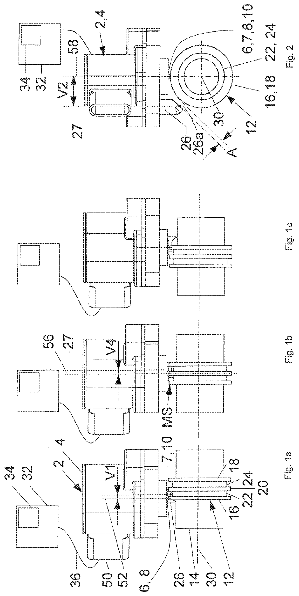
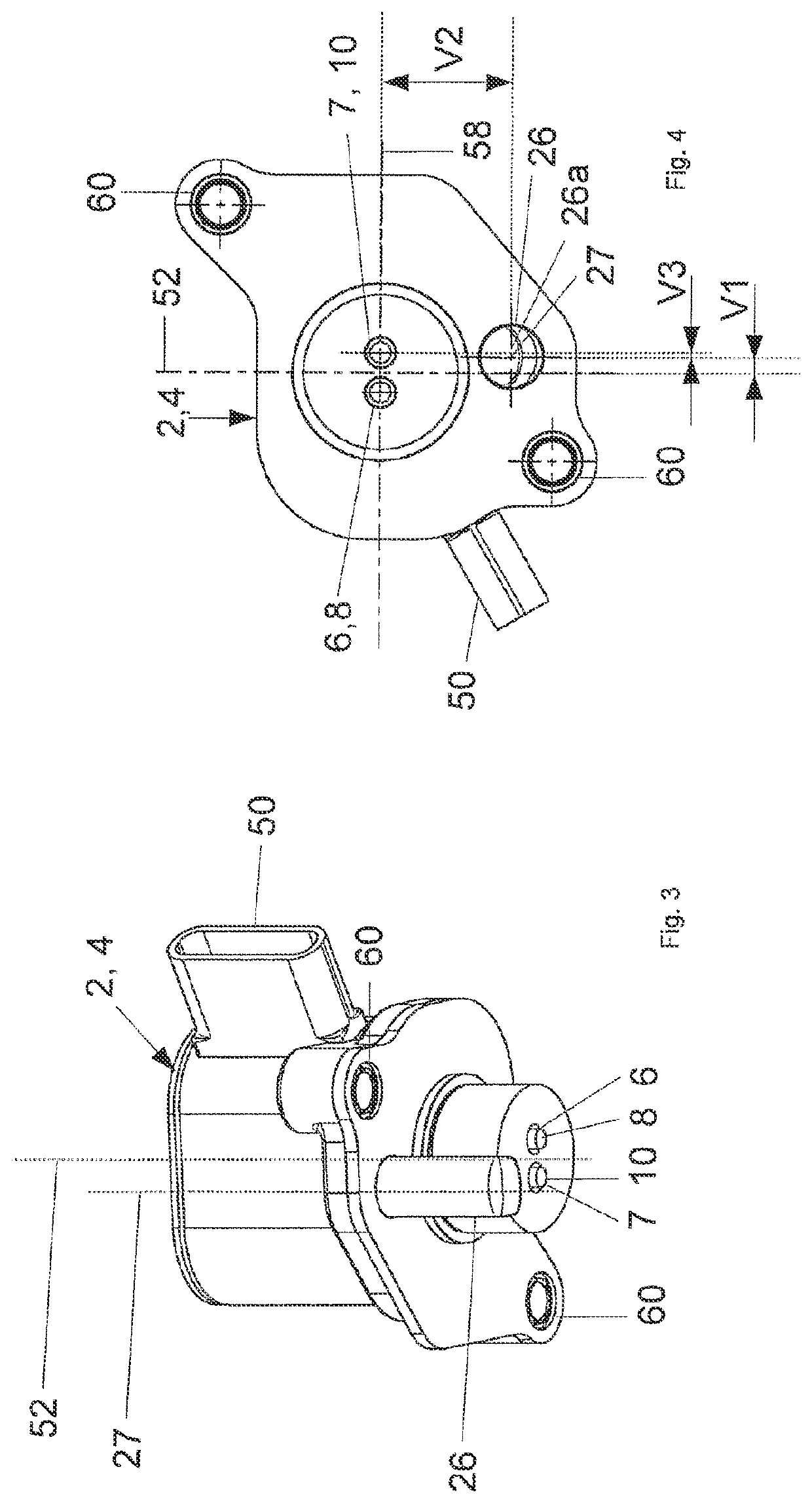
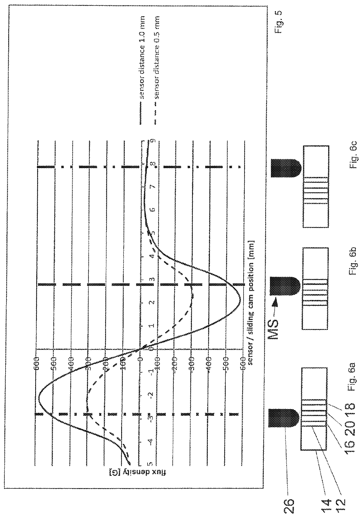
[0054]FIGS. 1a to 1c show identical elements in three different positions of a shift gate 12, wherein shift gate 12 is axially adjustable along an adjustment axis 30 in order to adjust a camshaft, for example. For the sake of clarity, not all figures of FIGS. 1a to 1c are provided with reference signs. However, with respect to the first embodiment, the same elements can be found in FIGS. 1a to 1c, 2, 3, 4 and 6a to 6c.

[0055]An actuator arrangement shown in FIGS. 1a to 6c comprises an electromagnetic actuator device 2 which is realized as a camshaft adjustment device. Actuator device 2 has a housing 4 within which two armature units (not shown) are drivable along the or parallel to the axial direction in response to an energization of two stationary, axially oriented coil units. Actuator device 2 thus comprises a plurality of electromagnetic actuator units which can be selectively controlled in order to independently apply an actuation force to a corresponding plurality of slides an...


PUM

PropertyMeasurementUnit
direct distanceaaaaaaaaaa
distanceaaaaaaaaaa

Abstract

The invention relates to an electromagnetic actuator arrangement comprising an electromagnetic actuator device (2), in particular a camshaft adjusting device, having a housing (4) and at least one armature unit which can be driven, in response to the energization of a stationary, axially aligned coil unit, in or parallel to the axial direction and which is designed to interact with at least one slide and / or tappet unit (6, 7) extending in the axial direction, in particular a tappet unit (6, 7) effecting a camshaft adjustment of an internal combustion engine, and at least one switching gate (12) which can be arranged on a slide cam (14) and through which a transverse central plane (56) passes, wherein the actuator device (2) comprises a detection device for contactless magnetic and / or electrical interaction with the switching gate (12), which detection device comprises at least one magnetic field and / or electric field detection means which is designed to produce and / or detect a detection field acting directly on the switching gate (12), and a detection field evaluation means (32) which is designed to determine the position of the switching gate (12) by means of the measured detection field, the magnetic field and / or electric field detection means being arranged at least partially outside the housing (4).

Description

BACKGROUND OF THE INVENTION[0001]The present invention relates to an electromagnetic actuator arrangement, to an electromagnetic actuator device and to a use of same.[0002]Such an actuator arrangement comprising an electromagnetic actuator device which is particularly suitable as a camshaft adjustment device and which has an armature unit which can be driven along the or parallel to the axial direction in response to an energization of a stationary, axially oriented coil unit is known from practice. The armature unit is configured to interact with a slide and / or plunger unit which extends in the axial direction, wherein, in particular, a camshaft adjustment of a combustion engine can thus be caused. To this end, the slide and / or plunger unit engages into a shift gate which can in particular be disposed on a sliding cam. In such a design, the shift gate is disposed at the circumference of the sliding cam. A transverse center plane can pass through the shift gate.[0003]To determine th...

Claims


Application Information

Patent Timeline
Patent Type & Authority Applications(United States)
IPC IPC(8): H01F7/08G01D5/14H01F7/121
CPCH01F7/081H01F2007/086H01F7/121G01D5/145F01L13/0036F01L2013/101F01L2013/0052F01L2820/04F01L2800/14H01F7/1607
Inventor RIGLING, TIMOOCZKOWSKI, MARKUS
Owner ETO MAGNETIC GMBH
Learn More