Pump embodied as a side channel pump

a side channel pump and pump body technology, applied in the direction of propellers, propulsive elements, water-acting propulsive elements, etc., can solve the problems of limited suction capacity and compression ratio, heating and noise, and reduce noise emission, improve compression, and high compression of the pump

Inactive Publication Date: 2006-08-15
LEYBOLD VAKUUM GMBH
View PDF15 Cites 10 Cited by
  • Summary
  • Abstract
  • Description
  • Claims
  • Application Information

AI Technical Summary

Benefits of technology

[0007]One advantage of the invention is improved compression in the side channel pump.
[0008]In one embodiment of the invention, the pump channel no longer extends like a screw thread about the rotor, rather than in an annular fashion. In this arrangement, the pump channel can comprise more than one winding, that is, the channel can include a plurality of windings. Moreover, the maximum pump channel length is not limited to one a single rotor circumference but, due to the helical arrangement, can be extended to a multiple of the rotor circumference and is just limited by the axial rotor length. The pump channel can extend continuously over a length of a plurality of windings without the pump channel being interrupted by loss-inflicted fluid inlets and outlets. Therefore, an undisturbed helical fluid flow develops in the pump channel over the entire pump channel length. Thus, a high compression of the pump is realized. Because of the omission of a plurality of fluid inlets and outlets, the noise emission is reduced as well.
[0009]The stator is configured as a surface area of a body of revolution. For example, the stator can be cylindrical, conical or parabolic. Therefore, the stator has a simple structure and can be produced inexpensively. An easily maintained side channel pump is realized that has a high compression and suction capacity, generates a fluid flow of low pulsation level, occupies a small installation space and is adapted to be produced easily and inexpensively. Since no oil seals are required, a fluid is delivered that is free of contaminations.
[0010]According to a preferred embodiment of the invention, the rotor comprises a channel wall laterally defining the pump channel, extending helically about the rotor. In the region of the pump channel, the stator is configured so as to have a smooth surface. Most walls of the pump channel are provided at the rotor side, i.e., they are moved in the pumping direction. Therefore, the fluid molecules are braked only at a single wall of the pump channel, namely at the wall formed by the stator. By this arrangement, the suction capacity of the pump is increased as well.
[0011]According to a preferred embodiment, the pump channel extends continuously over approximately the entire rotor length. The fluid inlet and outlet are provided at the end faces of the rotor, respectively. This means that a single self-contained compression stage extends over a plurality of windings over the entire length of the rotor. The front-face fluid inlet and the front-face fluid outlet are spatially separated from each other; this means that between the compression side and the suction side, there is no short circuit causing a pressure loss. With a single compression stage, a high compression and suction capacity can thus be realized.
[0012]According to a preferred embodiment, the rotor comprises several channel walls defining several pump channels parallel to each other. Hence, it is a multiple side channel pump having a correspondingly high suction capacity.

Problems solved by technology

The pressure losses caused in this manner produce heating and noise.
Due to the plurality of loss-inflicted fluid inlets and outlets, however, the suction capacity and the compression ratio are limited.

Method used


Image

  • Pump embodied as a side channel pump
  • Pump embodied as a side channel pump
  • Pump embodied as a side channel pump

Examples


first embodiment

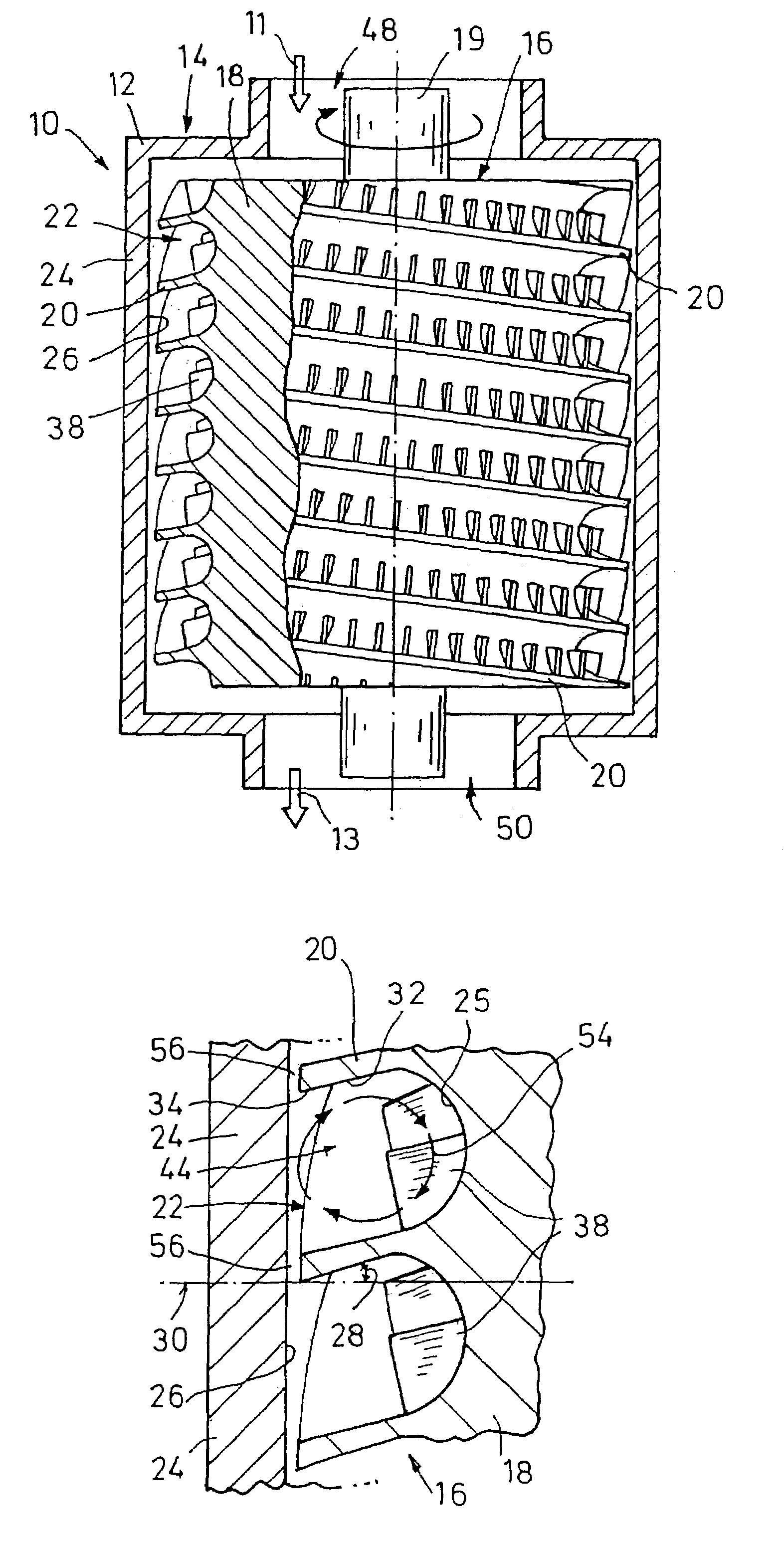
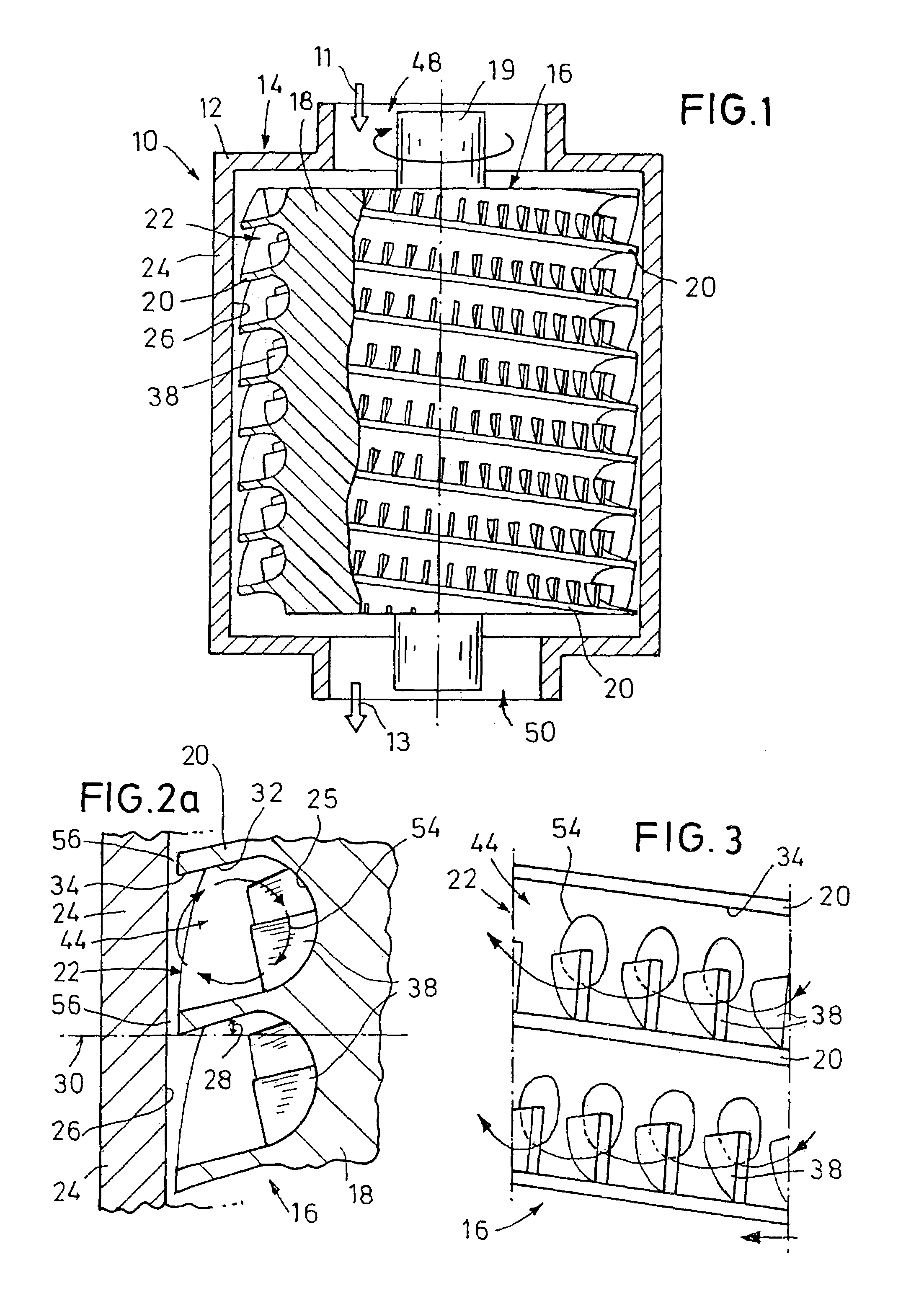
[0040]In FIG. 1, a pump 10 which is a side channel pump, for delivering a fluid, and preferably for delivering a gas, is illustrated. The pump 10 serves to produce a vacuum on a suction side 11 and to compress the fluid into medium vacuum or rough vacuum on a pressure side 13.

[0041]The side channel vacuum pump 10 is substantially formed by a stator 14 forming a fixed housing 12 and a driven rotor 16 in the stator housing 12. The rotor 16 is driven by an electric motor (not shown) by which the rotor 16 can be rotated at up to 80,000 revolutions / minute. The rotor 16 and the stator housing 12 are preferably made of metal, but may also be made of ceramics, be made of plastics or of a material coated with plastics. The operation of the vacuum pump 10 is preferably lubricant-free so that a contamination of the pumped fluid is avoided.

[0042]From the suction side 11 of the vacuum pump 10, the fluid flows through a fluid inlet 48 into the stator housing 12 at the one end face of the rotor 16...

second embodiment

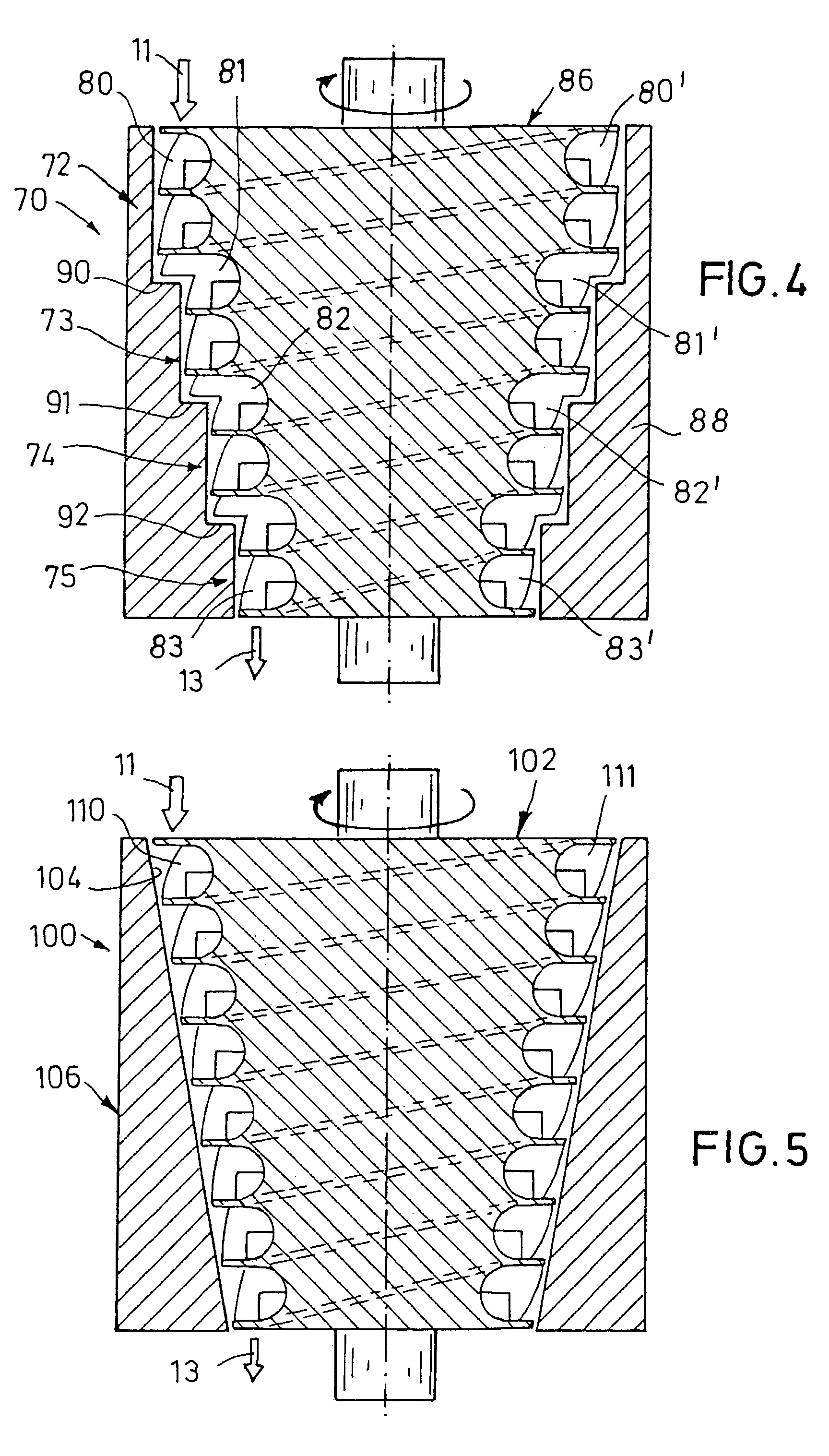
[0052]In FIG. 4, a double-lead side channel pump 70 is illustrated, where four steps 72, 73, 74, 75 with pump channels 80–83, 80′–83′ of different diameters are provided. Each step 72–75 comprises two parallel pump channels 80, 80′; 81, 81′; 82, 82′; 83, 83′, by which the suction capacity of the pump 70 is doubled in comparison with single-lead pumps. A rotor 86 as well as the a stator housing wall 88 are configured so as to be stepped such that the radius of the pump channels 80–83 respectively decreases to the pressure side 13 from step to step, whereas the cross-sectional area of the pump channels 80 B 83, 80′–83′ respectively remains the same. The height of each radial step 90, 91, 92 amounts to about one third of the radial height of a pump channel 80–83, 80′–83′. By limiting the height of the radial step to half of the radial pump channel height at maximum, the screw thread-like course of the pump channel is largely preserved in the region of the radial steps 90–92 as well. In...

third embodiment

[0053]In FIG. 5, a side channel pump 100 is illustrated where a rotor 102 as well as a housing wall inside 104 of a stator 106 are configured so as to conically taper from the suction side 11 to the pressure side 13. The rotor 102 comprises two pump channels 110 and 111 arranged next to each other on the rotor outside in a helical manner. The radial height of the two parallel pump channels 110, 111 is constant over the entire length of the pump channels 110, 111. By the tapering the rotor 102 and the stator 106 towards the pressure side, friction between rotor 102 and stator 106 is reduced.


PUM


Abstract

A side channel pump, preferably a vacuum pump, includes a driven rotor (16) and a fixed stator (14). The rotor (16) and the stator (14) define a pump channel circulating in a peripheral direction. Blades are fixed onto the rotor, protruding into the cross-section of the pump channel. The pump channel also includes a blade-free side channel (44). The pump channel (22) containing the side channel (44) extends in a helical manner around the rotor (16). The pump channel is advantageously not limited to the length of a winding but can have the length of substantially any number of uninterrupted windings. As a result, a high suction performance and a high compression ratio in the pump can be obtained.

Description

BACKGROUND OF THE INVENTION[0001]The invention relates to a side channel pump for supplying liquid and gaseous fluids as well as mixtures of liquid and gas.[0002]Among other things, side channel pumps are used for generating a vacuum. From EP-A-0 170 175, a side channel vacuum pump is known that includes several annularly extending pump channels limited by the rotor and by the stator each. At the rotor, blades are arranged, protruding into the respective pump channel cross-section. From radially inside, the blades protrude only into a portion of the pump channel cross-section so that the radial outer portion of the pump channel is free of blades. The blade-free portion of the pump channel is the side channel.[0003]During rotation of the rotor, the fluid molecules are seized by the blades and accelerated in circumferential direction. Due to the centrifugal force, the fluid molecules are moved outward into the blade-free side channel. In the side channel, the radially outward directed...

Claims


Application Information

Patent Timeline
Patent Type & Authority Patents(United States)
IPC IPC(8): F01D1/02F03B1/00F03D5/00F04D5/00F04D17/16F04D19/04F04D23/00F04D29/22F04D29/24F04D29/42F04D29/44F04D29/58
CPCF04D17/168F04D23/008F04D19/044
Inventor ENGLANDER, HEINRICHKLINGNER, PETERSECKEL, INGO
Owner LEYBOLD VAKUUM GMBH
Why Eureka
Try Eureka