Image generating apparatus and display device for layered display scheme based on location of eye of user

a technology of image generating apparatus and display device, which is applied in the direction of optics, electrical apparatus, instruments, etc., can solve the problems of image quality deterioration, image quality deterioration, and increase in so as to reduce resolution and increase computational complexity of generating images

Active Publication Date: 2018-04-17
SAMSUNG ELECTRONICS CO LTD
View PDF28 Cites 0 Cited by
  • Summary
  • Abstract
  • Description
  • Claims
  • Application Information

AI Technical Summary

Benefits of technology

[0007]One solution that may supplement the decrease in the resolution occurring in proportion to the number of directions of light desired to be expressed may be a layered display. The layered display may express different information based on a viewing location using at least two display panels. The layered display may display an image with a small depth at a maximum level of a resolution of an upper panel. The layered display may refer to a system that may include at least two layers of panels, without a lens or a barrier, and express different signals in different directions. However, as a number of images desired to be displayed increases, a computational complexity for generating images may increase.
[0008]The following description may implement a 3D image by tracking a location of an eye and displaying a desired image at a limited number of locations while maintaining an advantage of a layered display in displaying an image, and restricting an increase in a computational complexity with respect to expression of a number of views or directions. The following description may simultaneously resolve a degradation in a resolution in a conventional method and an increase in a computational complexity in a new method.
[0009]The following description relates to a layered display advantageous to resolution expression, among autostereoscopic three-dimensional (3D) displays. The layered display may display a desired image at a desired location using eye tracking, thereby reducing an operational complexity such that the layered display may be utilized more efficiently. To display an image of unlimited various directions, the operational complexity may increase. When it is impossible to express information of various directions, a method of minimizing a difference between information desired to be expressed and information to be expressed may be employed. In this example, a probability of the difference may increase and thus, a quality of image may decrease. Herein, by extremely restraining a location at which the image is desired to be displayed to a location of an eye, the operational complexity may be reduced and a value desired to be expressed and a value to be observed may be reduced, whereby a high-quality image may be displayed. In addition, by selecting an image desired to be display which is suitable for the location of the eye, a realistic experience similar to an actual object existing in a predetermined location in a 3D space may be provided to a viewer. Because a number of locations in the space desired to be express may be adjusted based on a number of viewers, an image may be displayed accordingly when locations of eyes of the plurality of viewers are obtained.

Problems solved by technology

However, in the autostereoscopic type method, a great number of views may be used to broaden a viewing area, an image quality may deteriorate due to a crosstalk between views, and the image quality may also deteriorate remarkably at a location outside of a determined optimal viewing distance.
However, as a number of images desired to be displayed increases, a computational complexity for generating images may increase.
The following description may simultaneously resolve a degradation in a resolution in a conventional method and an increase in a computational complexity in a new method.
To display an image of unlimited various directions, the operational complexity may increase.

Method used


Image

  • Image generating apparatus and display device for layered display scheme based on location of eye of user
  • Image generating apparatus and display device for layered display scheme based on location of eye of user
  • Image generating apparatus and display device for layered display scheme based on location of eye of user

Examples


Embodiment Construction

[0035]Reference will now be made in detail to embodiments, examples of which are illustrated in the accompanying drawings, wherein like reference numerals refer to like elements throughout. Example embodiments are described below to explain the present disclosure by referring to the figures.

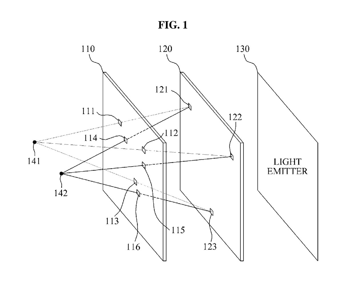
[0036]FIG. 1 illustrates a display device for displaying a three-dimensional (3D) image at a location of an eye of a user according to example embodiments.

[0037]Referring to FIG. 1, the display device may include a plurality of layers 110 and 120. The display device may display a 3D image by differentiating light to be recognized by a left eye 141 from light to be recognized by a right eye 142 of a user, using the plurality of layers 110 and 120. Hereinafter, a method of displaying a 3D image using the plurality of layers 110 and 120 in the display device will be described in detail.

[0038]The locations of the left eye 141 and the right eye 142 of the user may be tracked. To display a 3D image usi...


PUM


Abstract

An image generating apparatus and a display device for a layered display scheme based on a location of an eye of a user are provided, wherein the image generating apparatus may generate layer images for a three-dimensional (3D) image based on information related to pixels matched based on the location of the eye of the user.

Description

CROSS-REFERENCE TO RELATED APPLICATIONS[0001]This application claims the priority benefit of Korean Patent Application No. 10-2013-0116425, filed on Sep. 30, 2013, and Korean Patent Application No. 10-2013-0132712, filed on Nov. 4, 2013, in the Korean Intellectual Property Office, the disclosures of which are incorporated herein by reference.BACKGROUND[0002]1. Field[0003]Example embodiments of the following description relate to a scheme of generating an image to display a three-dimensional (3D) image and a 3D image display device.[0004]2. Description of the Related Art[0005]Among factors related to three-dimensional (3D) image recognition, the foremost factor is a disparity between images viewed by both eyes of a user. Methods of providing different images to both eyes of a user may be classified into a stereoscopic type and an autostereoscopic type. The stereoscopic type method may filter a desired image through division using a polarized light, time division, and a wavelength div...

Claims


Application Information

Patent Timeline
Patent Type & Authority Patents(United States)
IPC IPC(8): G06T19/00G02B27/26G02B27/22H04N13/00G02B30/25H04N13/122
CPCH04N13/0484G02B27/26H04N13/0495H04N13/0404H04N13/0468H04N13/0018H04N13/395H04N13/122H04N13/305H04N13/366H04N13/383G02B30/25
Inventor PARK, JU YONGNAM, DONG KYUNGLEE, SEOK
Owner SAMSUNG ELECTRONICS CO LTD
Why Eureka
Try Eureka