Depth estimating image capture device and image sensor

a technology of depth estimation and image capture, applied in measurement devices, stereoscopic photography, instruments, etc., to achieve the effect of reducing resolution

Active Publication Date: 2016-09-27
PANASONIC INTELLECTUAL PROPERTY MANAGEMENT CO LTD
View PDF20 Cites 0 Cited by
  • Summary
  • Abstract
  • Description
  • Claims
  • Application Information

AI Technical Summary

Benefits of technology

[0013]According to an embodiment of the present invention, information indicating the depth of a subject can be obtained using a different image sensor from a traditional one. Particularly, in an embodiment in which a mirror that reflects infrared light and transmits visible radiation and an infrared cut filter are combined, the depth information can be calculated based on the infrared light and an ordinary image without a decrease in resolution can be obtained based on the visible radiation. That is to say, both depth information and an ordinary image can be obtained at a time using a single-lens camera.

Problems solved by technology

But its resolution is determined by the number of micro lenses and should be lower than the resolution determined by the number of pixels of the image sensor, which is a problem.

Method used


Image

  • Depth estimating image capture device and image sensor
  • Depth estimating image capture device and image sensor
  • Depth estimating image capture device and image sensor

Examples


embodiment 1

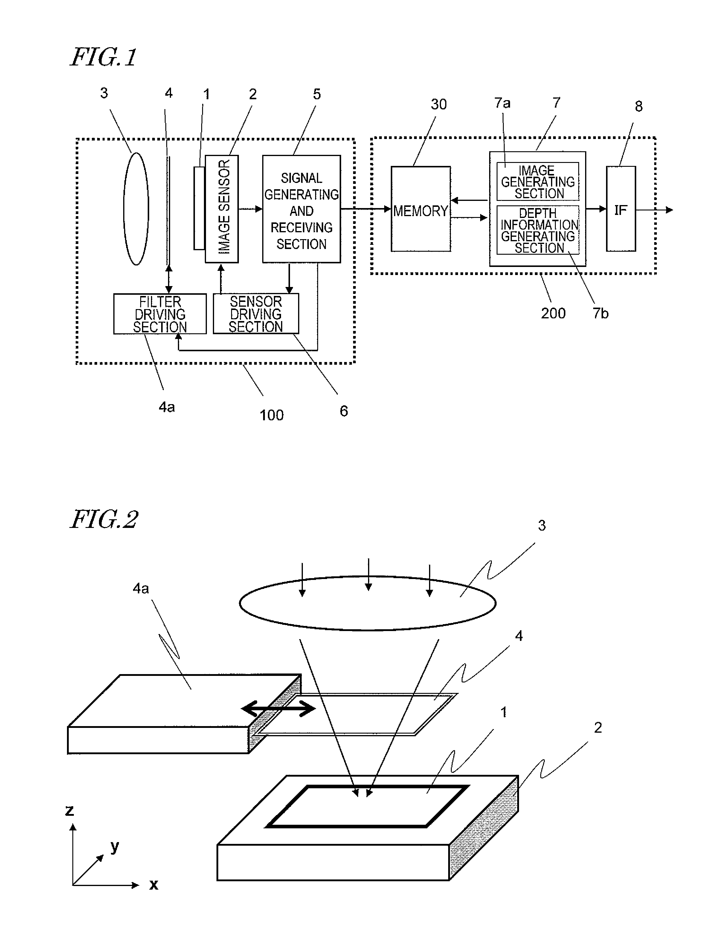
[0068]First of all, a depth estimating image capture device (which will be simply referred to herein as an “image capture device”) as a first embodiment will be described. Before this embodiment is described in detail, however, the basic idea of this embodiment will be described briefly.

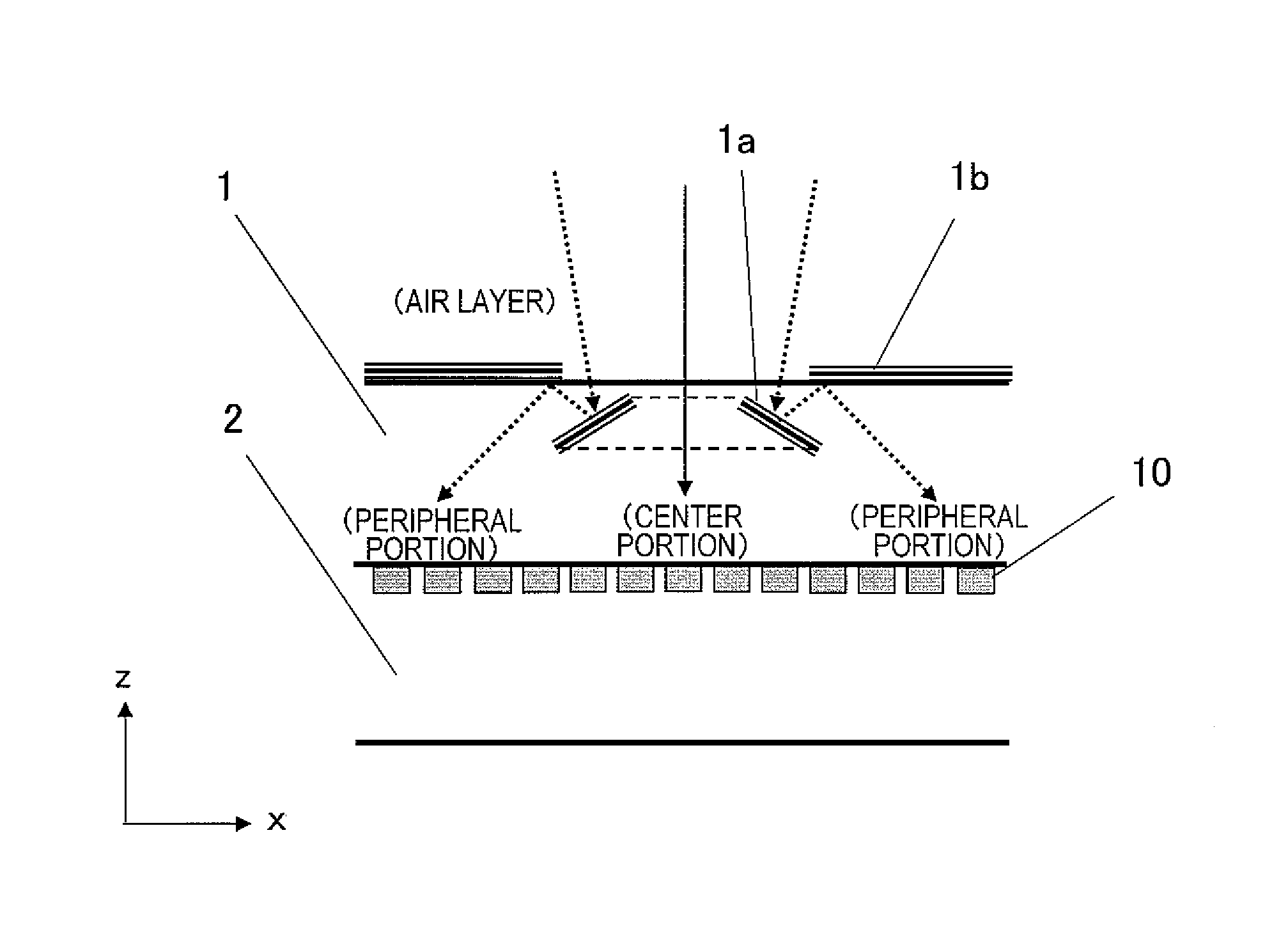
[0069]An image capture device according to this embodiment includes: an image sensor having a plurality of photosensitive cells arranged on its image capturing plane; an optical lens that is arranged to condense light on the image capturing plane of the image sensor; a light-transmitting member that is arranged on the image capturing plane; and a signal processing section that processes the output signals of the plurality of photosensitive cells. The light-transmitting member includes first and second mirrors that are arranged inside and on its upper surface, respectively. In this description, the “upper surface” refers herein to one of the surfaces of the light-transmitting member that is opposite t...

embodiment 2

[0104]Next, an image capture device as a second embodiment will be described. Before this embodiment is described in detail, however, the basic idea of the image capture device of this embodiment will be described briefly.

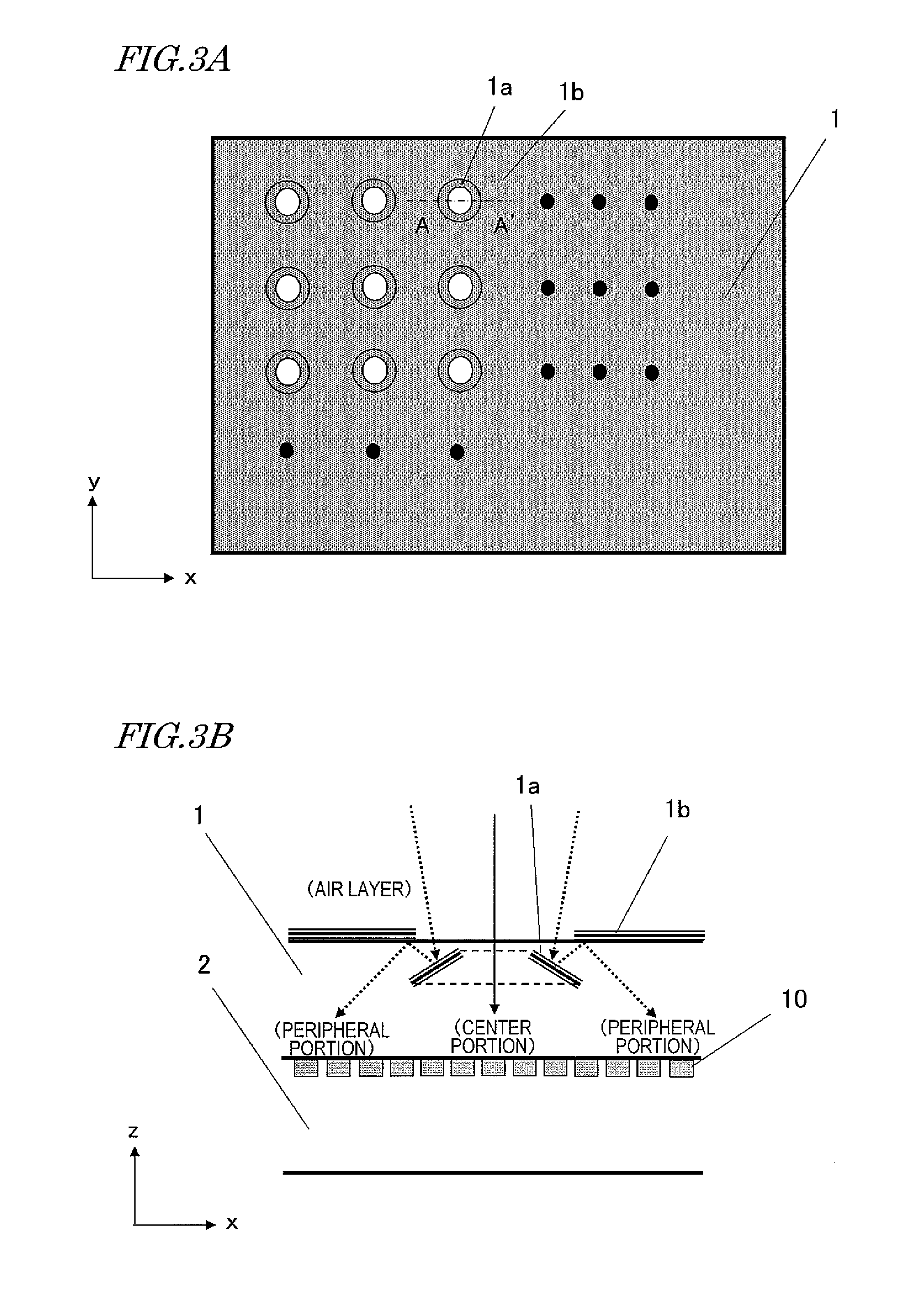
[0105]An image capture device according to this embodiment includes: an image sensor having a plurality of photosensitive cells arranged on its image capturing plane; an optical lens which is arranged to condense light on the image capturing plane of the image sensor; a light-transmitting member which is arranged on the image capturing plane; and a signal processing section which processes the output signals of the plurality of photosensitive cells. The light-transmitting member has a light beam splitting area that divides a light beam falling within a particular wavelength range, which has come from a portion of a subject through the optical lens, into at least three light beams. The light beam splitting area is made up of at least three partial areas including fi...


PUM


Abstract

A depth estimating image capture device includes: an image sensor; an optical lens; a light-transmitting member arranged on the plane; and a signal processing section. The member includes a first mirror inside to reflect the light at least partially and a second mirror with the same reflection property as the first mirror on its upper surface. The first mirror has a reflective surface tilted with respect to the upper surface of the member. The second mirror has a reflective surface that is parallel to the upper surface. The first and second mirrors and are arranged so that a light beam coming from a point on a subject through the lens is reflected from the first mirror and from the second mirror and irradiates some area on an image capturing plane to make the irradiated area change according to the depth of the point on the subject.

Description

TECHNICAL FIELD[0001]The present application relates to a single-lens three-dimensional image capturing technology for getting the depth information of a subject using a single optical system and a single image sensor.BACKGROUND ART[0002]Recently, the performance and functionality of digital cameras and digital movie cameras that use some solid-state image sensor such as a CCD and a CMOS (which will be sometimes simply referred to herein as an “image sensor”) have been enhanced to an astonishing degree. In particular, the size of a pixel structure for use in an image sensor has been further reduced these days thanks to rapid development of semiconductor device processing technologies, thus getting an even greater number of pixels and drivers integrated together in an image sensor. As a result, the resolution of an image sensor has lately increased rapidly from around one million pixels to ten million or more pixels in a matter of few years. On top of that, the quality of an image ca...

Claims


Application Information

Patent Timeline
Patent Type & Authority Patents(United States)
IPC IPC(8): H04N13/02G01B11/24G03B35/10
CPCH04N13/0235G01B11/24G03B35/10H04N13/0217H04N13/0271H04N13/218H04N13/271H04N13/236
Inventor HIRAMOTO, MASAOISHII, YASUNORIMONOBE, YUSUKE
Owner PANASONIC INTELLECTUAL PROPERTY MANAGEMENT CO LTD
Why Eureka
Try Eureka