Stereoscopic display device

a display device and stereoscopic technology, applied in the field of stereoscopic display devices, can solve the problems of reducing the switching speed between 2d display and 3d display, difficult to keep the cell thickness uniform, and deteriorating the crosstalk ratio, so as to prevent the deterioration of the crosstalk ratio and increase the brightness

Active Publication Date: 2017-09-05
SHARP KK
View PDF12 Cites 0 Cited by
  • Summary
  • Abstract
  • Description
  • Claims
  • Application Information

AI Technical Summary

Benefits of technology

[0005]It is an object of the present invention to provide a stereoscopic display device that is capable of, while preventing the crosstalk ratio from deteriorating, increasing the brightness during 3D display, switching 2D display and 3D display without decreases in the resolution, and achieving a switching response speed at the same level as that in the parallax barrier method.
[0007]The stereoscopic display device of the present invention is capable of, while preventing the crosstalk ratio from deteriorating, increasing the brightness during 3D display, switching 2D display and 3D display without decreases in the resolution, and achieving a switching response speed at the same level as that in the parallax barrier method.

Problems solved by technology

In the stereoscopic display device disclosed in Patent Documents 2 and 3, however, a desired lens effect could hardly be exhibited at boundary areas between adjacent two of the lenses, which causes the crosstalk ratio to deteriorate.
Besides, since the image separation is performed only by light condensing by the liquid crystal lenses, it is necessary that the liquid crystal layer has to have a greater thickness in order to achieve a satisfactory light condensing effect, which causes a problem that the switching speed for the switching between 2D display and 3D display decreases.
In addition to this, it is significantly difficult to keep the cell thickness uniform, which causes a problem of poor mass producibility.

Method used


Image

  • Stereoscopic display device
  • Stereoscopic display device
  • Stereoscopic display device

Examples


embodiment 1

[Embodiment 1]

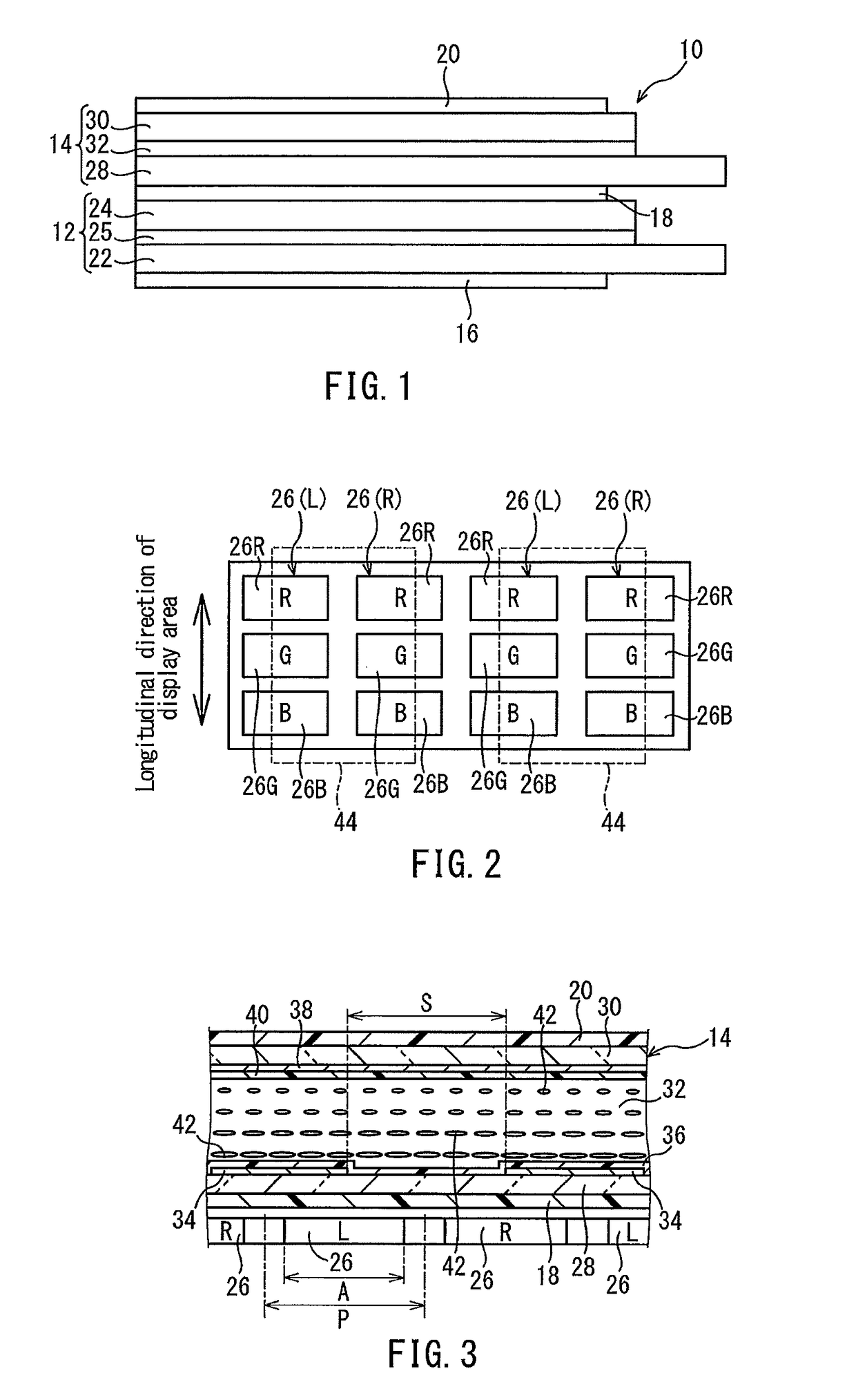
[0038]FIG. 1 shows a stereoscopic display device 10 as Embodiment 1 of the present invention. The stereoscopic display device 10 includes a display panel 12, a switching liquid crystal panel 14, and polarizing plates 16, 18, and 20.

[0039]The display panel 12 is a liquid crystal panel. The display panel 12 includes an active matrix substrate 22, a counter substrate 24, and a liquid crystal layer 25 sealed between these substrates 22 and 24. In the display panel 12, the liquid crystal is in an arbitrary operation mode.

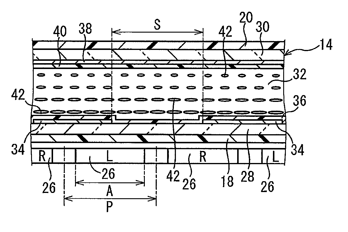
[0040]The display panel 12 includes a plurality of pixels 26, as shown in FIGS. 2 and 3. The plurality of pixels 26 are formed, for example, in matrix form. The area where the plurality of pixels 26 are formed is a display area of the display panel 12.

[0041]Each pixel 26 may include a plurality of subpixels 26R, 26G, and 26B, as shown in FIG. 2. In the example shown in FIG. 2, red pixels 26R, green pixels 26G and blue pixels 26B are used as the plurality of...

application example

[Application Example of Embodiment 1]

[0078]Though Embodiment 1 has a configuration in which a plurality of subpixels 26R, 26G, and 26B are arrayed in the longitudinal direction of the display area of the display panel 12, the present application example has a configuration in which a plurality of subpixels 26R, 26G, and 26B are arrayed in the lateral direction of the display area of the display panel 12, as shown in FIG. 14. In this case, as shown in FIG. 14, the subpixels contributing to the display of a left eye image and the subpixels contributing to the display of a right eye image are arrayed alternately in the lateral direction of the display area of the display panel 12. In the present application example, “A” in Formula (1) described in the explanation of Embodiment 1 represents the opening width of the subpixels (the dimension thereof in the direction in which the transmission parts 46 and the light-shielding parts 44 are arrayed alternately), and “P” represents the interva...

embodiment 2

[Embodiment 2]

[0079]A stereoscopic display device 50 as Embodiment 2 of the present invention is explained with reference toFIG. 15. The stereoscopic display device 50 of the present embodiment is different from the stereoscopic display device 10 of Embodiment 1 in that a λ / 2 plate 52 is arranged between the polarizing plate 18 and the switching liquid crystal panel 14.

[0080]In the present embodiment, as shown in FIG. 16, an angle δ formed between the transmission axis D4 of the polarizing plate 18 and the reference line L is 63°. The reason why the angle δ is 63° is that the display panel 12 is a liquid crystal panel of the ASV type (in which the operation mode of the liquid crystal is the VA mode and the CPA type). In the liquid crystal panel of the ASV type, preferable viewing angle characteristics are obtained when the angle δ is 63°. The angle o formed between the slow axis D5 of the λ / 2 plate 52 and the reference line L is 54°. The angle β formed between the alignment axis D2 ...


PUM

PropertyMeasurementUnit
angleaaaaaaaaaa
angleaaaaaaaaaa
voltageaaaaaaaaaa

Abstract

Provide is a stereoscopic display device that is capable of, while preventing the crosstalk ratio from deteriorating, increasing the brightness during 3D display, switching 2D display and 3D display without decreases in the resolution, and achieving a switching response speed at the same level as that in the parallax barrier method. A switching liquid crystal panel (14) includes: a pair of substrates (28, 30); a liquid crystal layer (32) sealed between the substrates in pair (28, 30); a common electrode (38) formed over an entirety of an area where a parallax barrier (48) is realized on the substrate (30); and a plurality of drive electrodes (34) formed on the substrate (28), the drive electrodes (34), in collaboration with the common electrode (38), forming light-shielding parts (44) when a voltage is applied thereto, wherein the transmission parts (46) has an opening width that is equal to or greater than an opening width of the pixels (26) in a direction in which the transmission parts (46) and the light-shielding parts (44) are arrayed alternately.

Description

TECHNICAL FIELD[0001]The present invention relates to a stereoscopic display device including a switching liquid crystal panel.BACKGROUND ART[0002]As a method for allowing a viewer to view stereoscopic images without using special glasses, the parallax barrier method and the lenticular lens method have been known since before. For example, JP2004-264760A (Patent Document 1) discloses a stereoscopic video display device that includes a switching liquid crystal panel that is capable of realizing a parallax barrier in which openings for transmitting light and light-shielding parts for blocking light are arrayed alternately. In the parallax barrier method, however, though it is possible to switch 2D display and 3D display from one to the other without a decrease in the resolution during 2D display, brightness during 3D display is 50% or less as compared with that during 2D display, due to the left-right image separation necessary for stereoscopic display, which is achieved by blocking l...

Claims


Application Information

Patent Timeline
Patent Type & Authority Patents(United States)
IPC IPC(8): G02F1/1335H04N13/04G02B27/22G03B35/24G02F1/1347G02F1/1343G02B30/31
CPCG02B27/2214G02B27/22G02F1/1347G03B35/24H04N13/0409H04N13/0454G02B27/225G02F2001/134318H04N13/31H04N13/359G02F1/134318G02B30/31G02B30/27
Inventor MURAO, TAKEHIROYOSHINO, TAKUTOFUKUSHIMA, HIROSHITAKATANI, TOMOO
Owner SHARP KK
Why Eureka
Try Eureka