Optical element and projection-type image display apparatus

Active Publication Date: 2020-09-10
SEIKO EPSON CORP
View PDF0 Cites 0 Cited by
  • Summary
  • Abstract
  • Description
  • Claims
  • Application Information

AI Technical Summary

Benefits of technology

[0080]In the projection-type image display apparatus 1A according to the present example, the optical element 3A has the concave reflective surface 12 and the convex second transmissive surface 13 protruding toward the magnifying side. The optical element 3A therefore allows the light flux reflected off the reflective surface 12 to be refracted by the second transmissive surface 13. The focal length of the optical element 3A, that is, the projection distance is therefore readily shortened.
[0081]In the optical element 3A, the reflective surface 12 and the second transmissive surface 13 are each an aspheric surface. Further, the surface numbers 3, 5, 7, and 9 represent joint surfaces at which the first member section 31 and the second member section 32 having different refractive indices are joined to each other and which each have a curved shape. Aberrations produced by the optical element 3A can therefore be suppressed.
[0082]FIGS. 8 to 11 each show magnifying-side MTFs of the optical element 3A. The MTFs were calculated under the following conditions: The image formation plane was divided along the axis Y; and the resultant halves were each divided into 25 areas. The horizontal axes of FIGS. 8 to 11 each represent the spatial frequency. A spatial frequency of 30 cycles corresponds to a resolution of 16.7 μm. The vertical axes of FIGS. 8 to 11 each represent a contrast reproduction ratio. Light rays used in the calculation of the MTFs are so weighted that the weighting ratio among light rays having a wavelength of 620 nm, light rays having a wavelength of 550 nm, and light rays having a wavelength of 470 nm is 2:7:1. In FIG. 9, the light rays used in the calculation of the MTFs are the light rays having the wavelength of 620 nm. That is, FIG. 9 shows the resolution of red light rays. In FIG. 10, the light rays used in the calculation of the MTFs are the light rays having the wavelength of 550 nm. That is, FIG. 10 shows the resolution of green light rays. In FIG. 11, the light rays used in the calculation of the MTFs are the light rays having the wavelength of 470 nm. That is, FIG. 11 shows the resolution of blue light rays. The present example demonstrates that a decrease in the resolution is suppressed, that a decrease in MTFs at each of the colors is also suppressed, and that chromatic aberrations are satisfactorily corrected, as shown in FIGS. 8 to 11.
[0083]FIG. 12 is a spot diagram showing spots produced by the optical element 3A. In the spot diagram shown in FIG. 12, the spots are small. The aberrations are therefore satisfactorily corrected in the present

Problems solved by technology

In this case, however, the number of optical element

Method used


Image

  • Optical element and projection-type image display apparatus
  • Optical element and projection-type image display apparatus
  • Optical element and projection-type image display apparatus

Examples


Example

Example 1

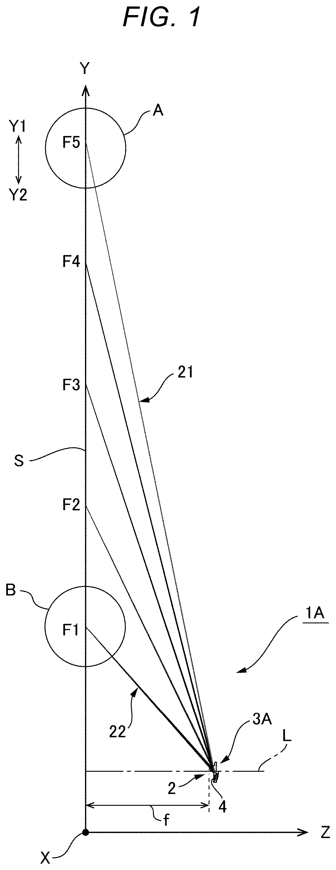
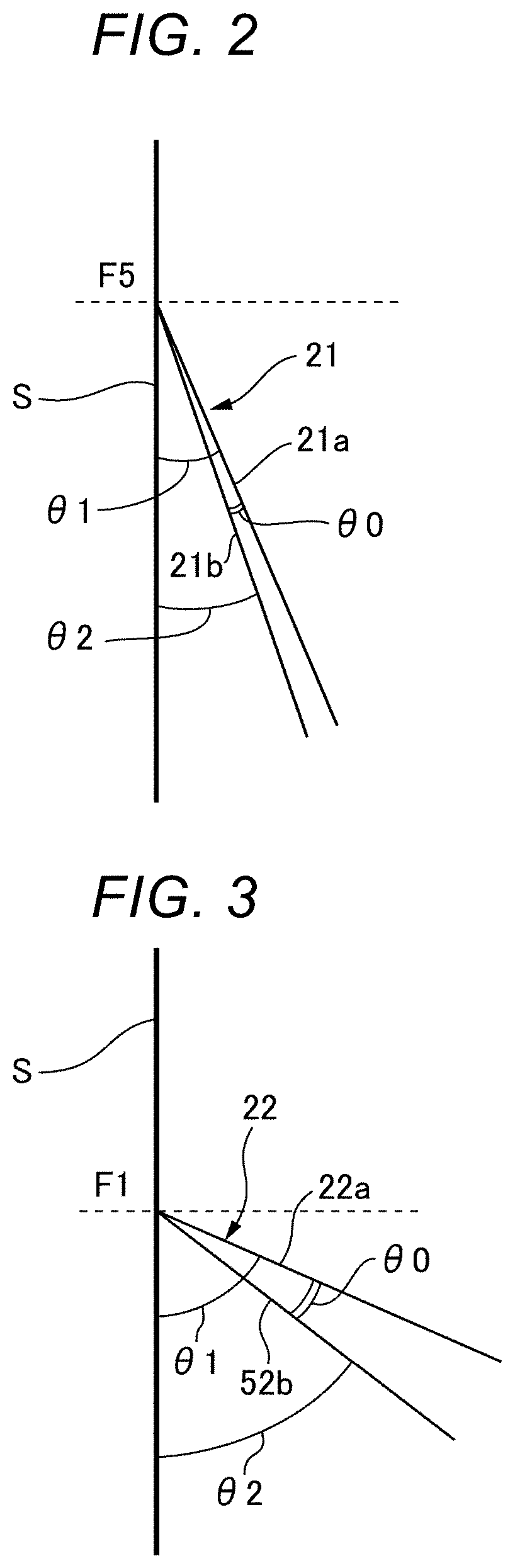
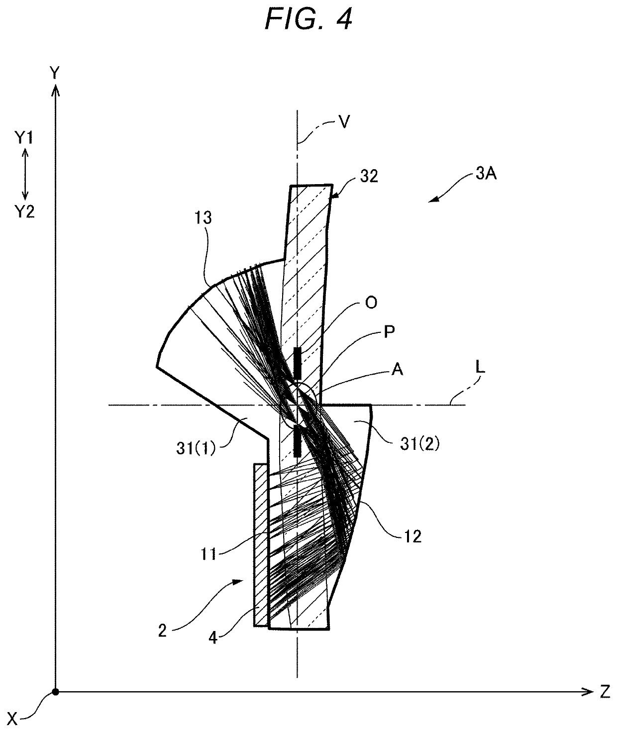
[0059]FIG. 1 is a light ray diagram showing the entirety of a projection-type image display apparatus according to Example 1 of the present disclosure. FIG. 2 is a partially enlarged view of the portion A in FIG. 1. The portion A is a largest image height portion and therearound on a screen in the direction along an axis Y. FIG. 3 is a partially enlarged view of the portion B in FIG. 1. The portion B is a smallest image height portion and therearound on the screen in the direction along the axis Y. The large image height portion A contains an image position farthest from the optical axis of an optical element and is an uppermost image position on the screen. The small image height portion B contains an image position nearest from the optical axis of the optical element and is a lowermost image position on the screen. FIG. 4 is a light ray diagram showing light rays traveling through the optical element. FIG. 5 describes an imaginary line specified in the optical element.

[00...

Example

[0101]A projection-type image display apparatus according to Embodiment 2 will next be described. FIG. 22 is a light ray diagram showing the entire projection-type image display apparatus according to Example 2. FIG. 23 is a light ray diagram showing light rays traveling through an optical element. FIG. 24 describes the imaginary line P specified in the optical element. In a projection-type image display apparatus 1B according to the present example shown in FIGS. 22 to 24 each viewed along the direction parallel to the axisX, the imaginary line P specified in an optical element 3B inclines with respect to the imaginary vertical line V, but the other configurations are the same as those of the projection-type image display apparatus 1A according to Embodiment 1. Configurations corresponding to those of the projection-type image display apparatus 1A according to Embodiment 1 therefore have the same reference characters.

[0102]The projection-type image display apparatus 1B according to...

Example

[0131]A projection-type image display apparatus 1C according to Embodiment 3 will next be described. FIG. 32 is a light ray diagram showing the entire projection-type image display apparatus 1C according to Example 3. FIG. 33 is a light ray diagram showing light rays traveling through an optical element of the projection-type image display apparatus 1C according to Example 3. FIG. 34 describes the imaginary line P specified in the optical element. In the projection-type image display apparatus 1C according to the present example shown in FIGS. 32 to 34 each viewed along the direction parallel to the axis X, the imaginary line P specified in an optical element 3C inclines with respect to the imaginary vertical line V, but the other configurations are the same as those of the projection-type image display apparatus 1A according to Embodiment 1. Configurations corresponding to those of the projection-type image display apparatus 1A according to Embodiment 1 therefore have the same refe...


PUM


Abstract

An optical element has a first member having a first refractive index and a second member having a second refractive index different from the first refractive index. The optical element has a first transmissive surface, a reflective surface, and a second transmissive surface arranged from a demagnifying side toward a magnifying side in order. The first transmissive surface and the reflective surface are located in one side with respect to an optical axis of the optical element. The second transmissive surface is located in the other side with respect to the optical axis of the optical element. the reflective surface has a concave shape.

Description

[0001]The present application is based on, and claims priority from JP Application Serial Number 2019-039255, filed Mar. 5, 2019, the disclosure of which is hereby incorporated by reference herein in its entirety.BACKGROUND1. Technical Field[0002]The present disclosure relates to an optical element having a concave reflective surface and further relates to a projection-type image display apparatus.2. Related Art[0003]JP-A-2010-20344 describes a projection-type image display apparatus that enlarges and projects a projection image formed by an image formation section via a projection system. The projection system in JP-A-2010-20344 is formed of a first optical system and a second optical system sequentially arranged from the demagnifying side toward the magnifying side. The first optical system includes a refractive optical system. The second optical system is formed of a reflection mirror having a concave reflective surface. The image formation section includes a light source and a l...

Claims


Application Information

Patent Timeline
IPC IPC(8): G03B21/28G02B17/08
CPCG03B21/28G02B17/086G03B21/006G02B17/08G03B21/142
Inventor MORIKUNI, EIJI
Owner SEIKO EPSON CORP
Why Eureka
Try Eureka