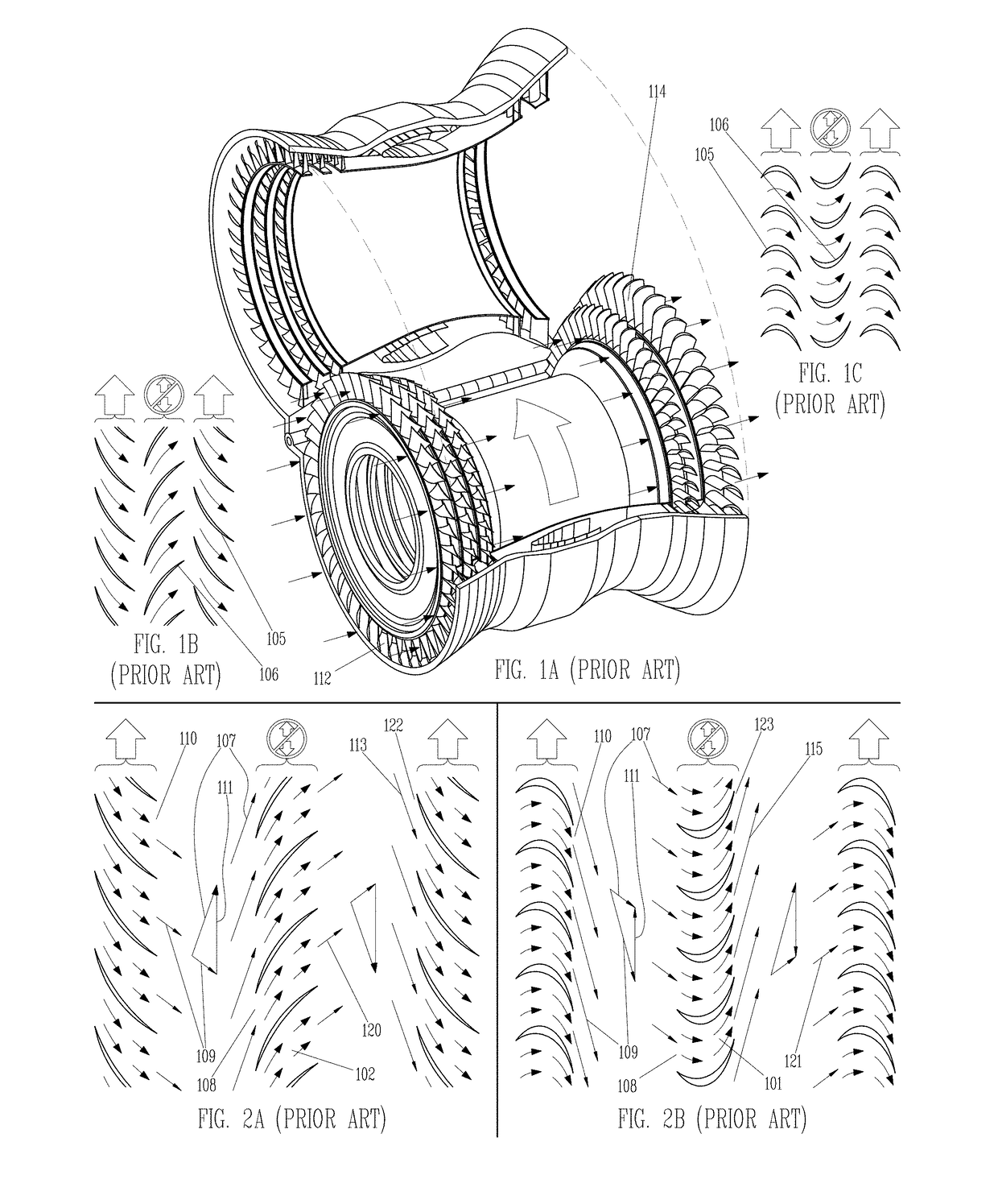
(FIGS. 2A and 2B) Total dependence on converging or diverging flow passages creates two major problems.
First, all turbomachines suffer substantial loss of energy by the action of velocity-dependent mechanisms.
High fluid shearing rates cause substantial viscous energy loss and may result in the formation of turbulent boundary layers that make the problem worse.
Where compressible fluids move past solid structures at transonic or supersonic velocities, shock waves will form that cause further energy loss.
To top it off, the diverging flow passages in compressors can suffer the counter-productive effects of fluid boundary layers thickening and possibly separating from their fluid-solid interfaces, creating zones of flow reversal and re-circulation and generally causing unacceptable flow instability.
Turbulent boundary layers can only partially mitigate the boundary layer separation problem.
This is why compressors are generally larger and less efficient than equivalent turbines.
The net result of viscous shear loss, turbulent loss, shock loss and boundary layer thickening / separation is a substantial reduction in machine efficiency.
Although 10-20% may sound relatively small, such losses can have major consequences for the operation of these devices, as will be demonstrated.
The second major problem caused by converging or diverging flow passages is the relative inability of turbomachines to handle widely varying fluid flow rates without also changing blade RPM proportionately.
Since blade RPM determines the amount of total fluid pressure rise or drop that can be produced across a given machine, this problem is therefore referred to as the flow-pressure coupling problem in this specification.
This becomes a problem because smooth flow into a blade set requires that blade entry surfaces 129 near leading edges be substantially aligned with flow approach vectors.
Although some newer turbomachinery designs incorporate variable-angle stationary blades to accommodate variable flow approach vectors, orientations of rotating blades cannot realistically be altered.
This will cause unacceptable energy losses and, in the case of compressors, could de-stabilize operation.
Major operational constraints result from the problem of velocity-dependent energy loss in turbomachines.
The isentropic compression generally occurs within a turbocompressor and requires consumption of the shaft power produced by the turbine.
This trend has compounded the energy loss problem in those components, because at higher cycle pressure ratios the shaft power transmitted from turbine to compressor can be very large relative to the thermal power input at the high-temperature heat addition.
If the same engine transmits three times as much power on shafts as it takes in as thermal input, the 10% losses will manifest as an efficiency loss of roughly 63% to the engine.
Very high turbine intake temperatures are a reality in almost all modern gas turbine designs and are one of the primary drivers of design and manufacturing costs, of maintenance / overhaul requirements and of lifespan limitations for turbine-type engines.
Such an engineering feat can only be accomplished through use of exotic metallurgy and materials technologies, intricate film cooling techniques, exacting structural design and testing, active engine management, rigorous inspection and maintenance schedules, etc.
Although an ideal engine is impossible to build, large reductions in turbomachinery component losses can translate into very large gains in engine efficiency before turbine intake temperatures again become a serious issue.
Ground vehicle engines typically spend most of their running time at a setting well below their maximum output, a mode in which a gas turbine cannot operate near peak efficiency.
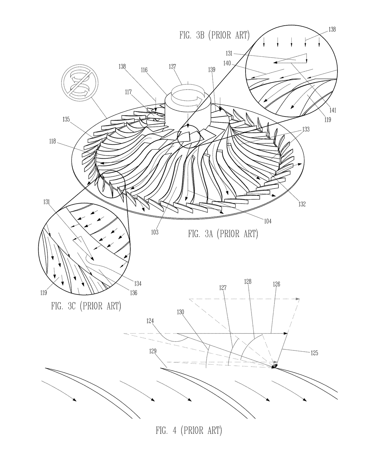
(FIGS. 3A through 3C) Unfortunately, the advantages of this type of flow passage are not fully leveraged.
(FIGS. 3A through 3C) This large kinetic energy fraction at the outer rim is the primary cause of the impeller entry and exit problem.
(FIGS. 3A through 3C) The secondary cause of the impeller entry and exit problem is the kinetic energy fraction at the hub.
Well over half of the useful output of a centrifugal compressor or turbine is produced within converging or diverging flow passages, and is therefore subject to the same velocity-dependent energy loss and flow-pressure coupling that plague axial-flow machines.
A solution to the impeller entry and exit problem is needed, because the advantages of rotating radial flow passages cannot be fully realized if those passages do less than half the total work.
This cannot be done with current radial-flow technology due to the impeller entry and exit problem.

