Motor

a technology of motors and components, applied in the field of motors, can solve the problems of increasing the manufacturing cost of the motor and the complex manufacturing process of the motor, and achieve the effect of reducing or preventing the adhesion of liquid droplets

Active Publication Date: 2018-05-01
NIDEC CORP
View PDF24 Cites 0 Cited by
  • Summary
  • Abstract
  • Description
  • Claims
  • Application Information

AI Technical Summary

Benefits of technology

[0008]According to various preferred embodiments of the present invention, liquid droplets adhering to the connector member flow down the flow path groove and the flow path surface and are discharged to the outside of the back cover through the through-hole. Therefore, the motor according to various preferred embodiments of the present invention significantly reduce or prevent adhesion of the liquid droplets to the brush without the need for an O-ring or a gasket as an essential component.

Problems solved by technology

In addition, when the number of components of the motor increases, the manufacturing process of the motor becomes complex and the manufacturing cost of the motor also increases.

Method used


Image

  • Motor
  • Motor
  • Motor

Examples


Embodiment Construction

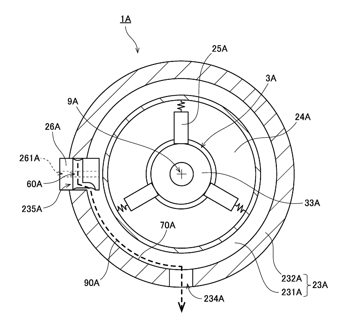
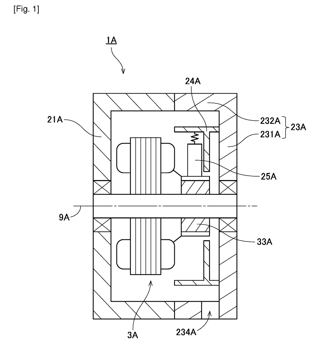
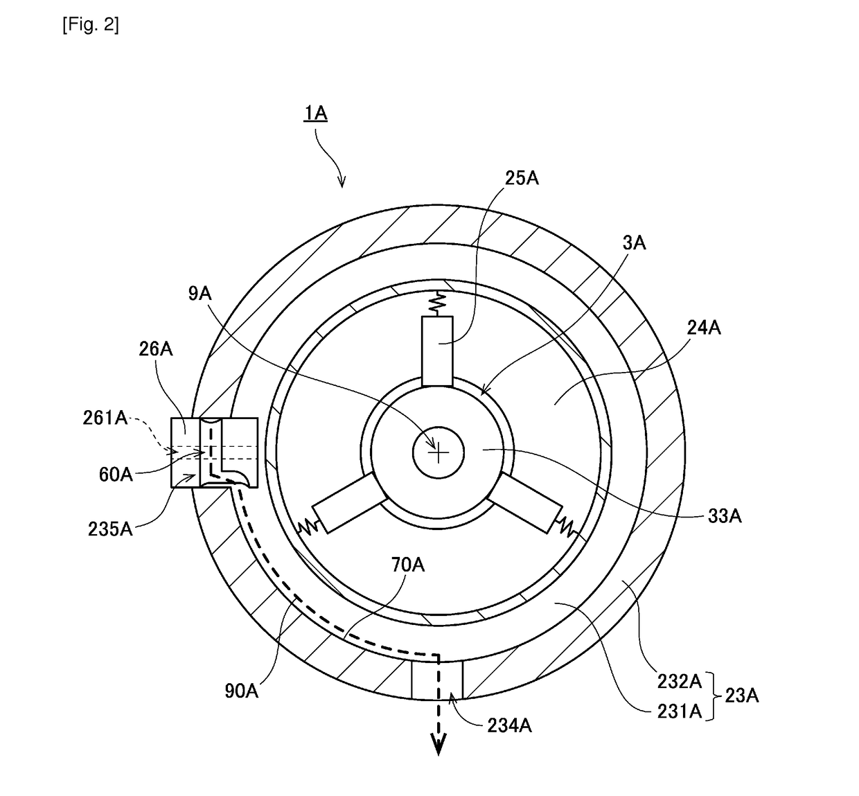
[0024]Hereinafter, exemplary preferred embodiments of the present invention will be described. In addition, in the present invention, a direction parallel or substantially parallel to the center axis of a motor is referred to as an “axial direction”, a direction perpendicular or substantially perpendicular to the center axis of the motor is referred to as a “radial direction”, and a direction along the arc about the center axis of the motor as the center is referred to as a “circumferential direction”. In addition, in the present invention, shapes and positional relationships of portions are described assuming that the axial direction is a forward and rearward direction and a housing side with respect to a back cover is a forward direction. In addition, a “parallel direction” in the present invention includes both a parallel direction and a substantially parallel direction. In addition, a “perpendicular” in the present invention includes both a perpendicular or substantially perpend...


PUM


Abstract

A motor includes a housing, a back cover, a brush card, a brush, and a connector member. The back cover includes a first rear wall portion and a first peripheral wall portion. The first peripheral wall portion includes a through-hole and a cut-out. The through-hole vertically penetrates through the first peripheral wall portion at or near a lower end portion of the first peripheral wall portion. The cut-out is disposed farther on an upper side than the through-hole. The connector member is fitted into the cut-out. An outer surface of the connector member is provided with a flow path groove that extends in both peripheral and axial directions. The motor includes a flow path surface on an inner surface of the back cover. The flow path surface continues from a portion that opposes the flow path groove on a lower side of the flow path groove to the through-hole.

Description

BACKGROUND OF THE INVENTION[0001]1. Field of the Invention[0002]The present invention relates to a motor.[0003]2. Description of the Related Art[0004]Hitherto, a motor having a brush is known. The structure of the motor having a brush is described, for example, in Japanese Patent No. 3971349. The motor in Japanese Patent No. 3971349 has a rotatable armature and a brush which comes into sliding contact with a commutator of the armature (Paragraphs [0018] and [0019] of Japanese Patent No. 3971349). In addition, the brush in Japanese Patent No. 3971349 is connected to an external power supply and supplies power to the armature via the commutator (Paragraph [0019] of Japanese Patent No. 3971349).[0005]There may be a case where the motor having the brush is used in an environment in which liquid droplets are likely to be present, for example, the inside of a vehicle. In this case, it is preferable that liquid droplets be prevented from adhering to the brush, which is a conductor. In addi...

Claims


Application Information

Patent Timeline
Patent Type & Authority Patents(United States)
IPC IPC(8): H02K5/00H02K3/44H02K13/00H02K3/28H02K5/14H02K5/132H02K5/04H02K5/12H02K5/10H02K5/128
CPCH02K3/44H02K13/006H02K3/28H02K2205/09H02K5/00H02K5/04H02K5/10H02K5/12H02K5/128H02K5/1285H02K5/132H02K5/14H02K5/141H02K5/143H02K5/146
Inventor SHIRAISHI, TAKASHIHIWA, TAKAHIROOSUGA, SHOHEI
Owner NIDEC CORP
Why Eureka
Try Eureka