
Dental forceps with a post for extracting teeth

a technology of teeth extraction and teeth socket, which is applied in the direction of dental forceps, etc., can solve the problems of tooth extraction devices that are often associated with pain and unpleasantness, damage to the socket of the extracted tooth, and unnecessary pain and discomfor

Inactive Publication Date: 2018-05-15
BIALOBRZESKI MARILYN
View PDF16 Cites 2 Cited by
  • Summary
  • Abstract
  • Description
  • Claims
  • Application Information

AI Technical Summary

Benefits of technology

The invention is a tooth extracting instrument that has two engaging members for grabbing the tooth. It also has a mechanism for adjusting the position of the instrument to align with the tooth. This allows for easier extraction of the tooth and reduces the risk of complications.

Problems solved by technology

The use of such devices to extract teeth is often associated with pain and unpleasantness.
This results in unnecessary pain and discomfort, as the tooth must be worked out, and often the use of such tools results in damage to the socket of the extracted tooth.
This makes the leverage point close to the tooth so it does not give as much leverage as my design.
Also, the post goes into the crossbar resulting in a greater possibility for the forceps to hit the front teeth when extracting a molar.
The crossbar is not stable and could move during the extraction.
The leverage of the patent '580 would be affected by the use of the rubber on the bottom of the crossbar because the rubber would flex, not giving a positive extraction.
For these reasons this patent '580 has not been successful.
However, the tooth extractor system described in the '454 patent suffered from a relatively complex assembly of parts what would have limited its usefulness.
For at least these reasons and perhaps others, the tooth extractor system described in the '454 patent apparently did not become widely established on the market.
This method, however, does not remove the tooth straight out and still might need to twist the tooth.
Various other dental forceps or so-called “fulcrum forceps” also exist in the prior art, which have found only limited success in the market.
However, none of these devices provide an acceptable tool for simplifying the tooth extraction procedure and minimizing pain and unpleasantness as a tooth is worked out.

Method used


Image

  • Dental forceps with a post for extracting teeth
  • Dental forceps with a post for extracting teeth
  • Dental forceps with a post for extracting teeth

Examples


Embodiment Construction

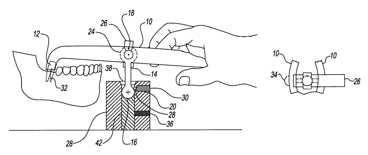
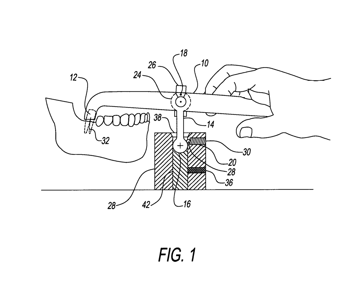
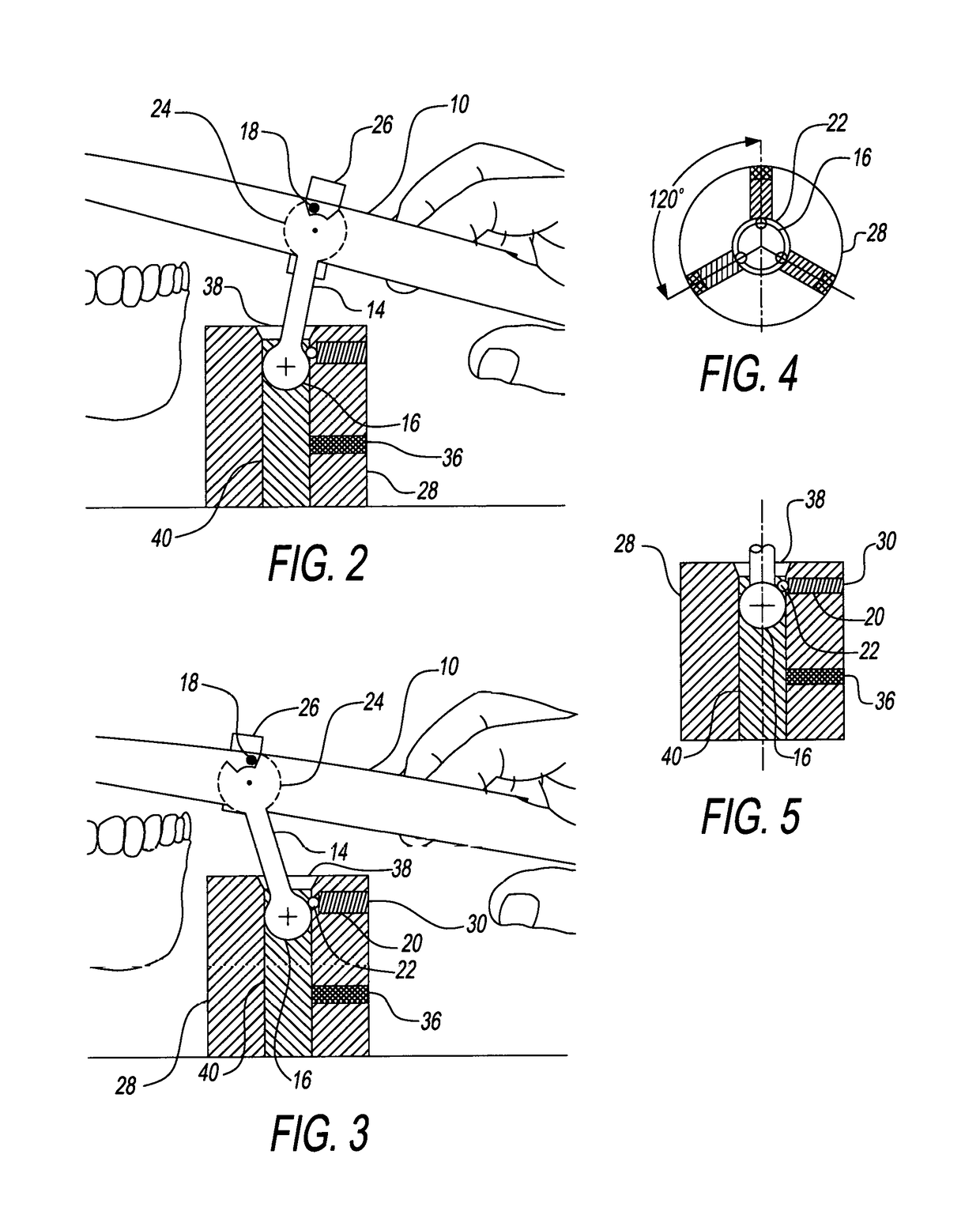
[0039]FIG. 1 shows a perspective view of the forceps 10, with a right side handle and left side handle having a post 14 with a post disc 24 on the upper part of the post 14. The post disc 24 is held in place by the post disc holder 26 that is lined up in the center of the forceps jaws 12. The post disc 24 has a slot in the top to form a stop when the stop pin 18 is screwed through the forceps 10 handle and into the post disc holder 26. The lower part of the post 14 has a post ball 16 that fits into the post ball holder 28. The post 14 is held in place in the post ball holder 28 by a ball bearing 22 held in place with a spring 20 and set screw 30 in three places around the post ball holder 28. There is a post ball holder center rod 40 that can be adjusted by a long set screw 36. When the forceps 10 is placed into the post ball holder 28 and is aligned with the tooth 32, that can be done by the counter sink opening 38 allowing the post to move, the dentist now has the leverage to extr...


PUM


Abstract

A dental forceps that include an elongated handle and a pair of tooth engaging members or jaws extending out of the one end of the handle and a post located in the handle with a disc at the top with a ball at the other end of the post. The post ball end inserts into the post ball holder to provide a stable support so that the dentist has leverage to extract the tooth straight out. The post disc and post ball provide the forceps with side-to-side and back-and-forth movement, thus allowing the forceps to align to the growth angle of the tooth to be extracted.

Description

CROSS-REFERENCE TO RELATED APPLICATION[0001]This application claims the benefit of Provisional patent application Ser. No. 62 / 388,547, filed 2016 Feb. 1 by the present inventor.FEDERALLY SPONSORED RESEARCH[0002]NoneSEQUENCE LISTING[0003]NoneBACKGROUNDField of Invention[0004]This invention is to change the way teeth are extracted by using a forceps with a post for greater leverage for the extraction.Prior Art[0005]A number of prior art devices exist for the purpose of extracting a tooth or removing a dental prosthesis, crowns and the like. The use of such devices to extract teeth is often associated with pain and unpleasantness. This invention and procedure is to extract teeth with less pain to the patient. Part of the pain originates from the simple tools that dentists currently use to extract teeth. Specifically, the forceps and elevators that are currently used by dentists require brute force to be applied by the dentist in removing the tooth. Dentists currently extract tooth twis...

Claims


Application Information

Patent Timeline
Patent Type & Authority Patents(United States)
IPC IPC(8): A61C3/14A61C3/16
CPCA61C3/14A61C3/162
Inventor BIALOBRZESKI, MARILYN
Owner BIALOBRZESKI MARILYN
Learn More