
Sealed and ventilated receptacle

a technology of sealed and ventilated receptacles, applied in the field of sealed receptacles, to achieve the effect of convenient use and convenient us

Active Publication Date: 2018-05-15
SQUICCIARINI ROBERT
View PDF7 Cites 4 Cited by
  • Summary
  • Abstract
  • Description
  • Claims
  • Application Information

AI Technical Summary

Benefits of technology

[0007]It is a further object of the invention to provide a receptacle for storing firefighter turnout gear that is easy and convenient to use.
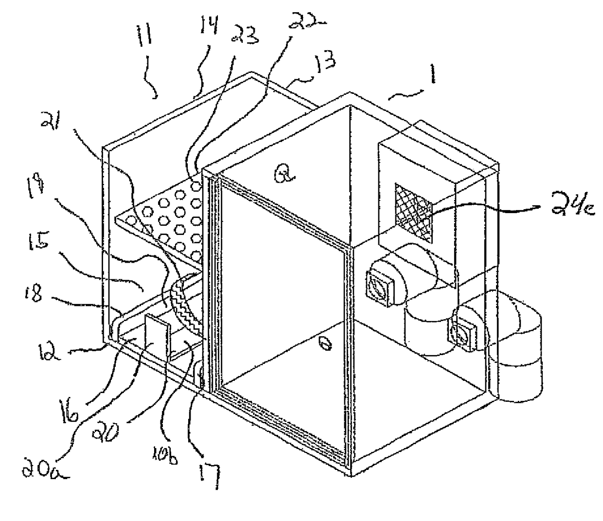
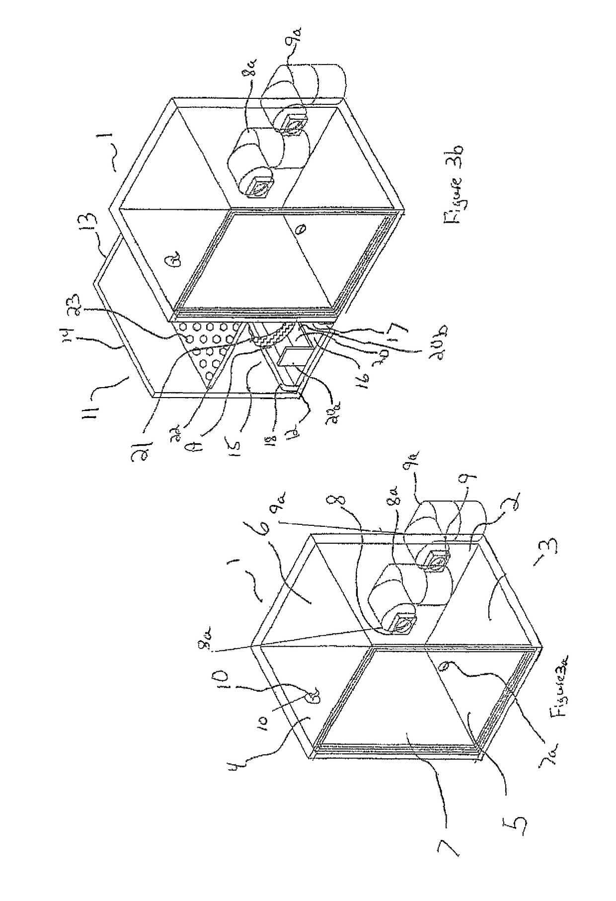
[0011]The present invention is directed to a receptacle for preferably storing firefighter turnout gear inside of a vehicle, such as a sports utility vehicle (“SUV”) or a fire engine, that complies with the NFPA regulations. The receptacle is preferably ventilated and sealed and generally includes a base, at least one sidewall extending from the base, and a top wall that covers the opposite end of the sidewall. A sealable door may be positioned on the sidewall to access the inside of the receptacle and to prevent any contaminants from exiting the receptacle. Ventilation means for providing fresh air to and removing stale air from the inside of the receptacle may also be included as well as a temperature control unit to regulate the climate inside of the receptacle. A hanging means, such as a hook, may be placed inside of the receptacle to allow a user to hang an item, such as the firefighter protective coat and / or trousers. In addition, the receptacle may include further storage means, such as having at least one shelf disposed inside of the receptacle and / or having more than one hook on any of the walls and / or shelves of the receptacle for hanging items therein.

Problems solved by technology

However, since the turnout gear is exposed to the smoke and contaminants that are present in the hazardous environments that firefighters respond to, the Federal National Fire Protection Association (“NFPA”) has passed regulations that require the turnout gear to be stored in a special fashion.

Method used


Image

  • Sealed and ventilated receptacle
  • Sealed and ventilated receptacle
  • Sealed and ventilated receptacle

Examples


Embodiment Construction

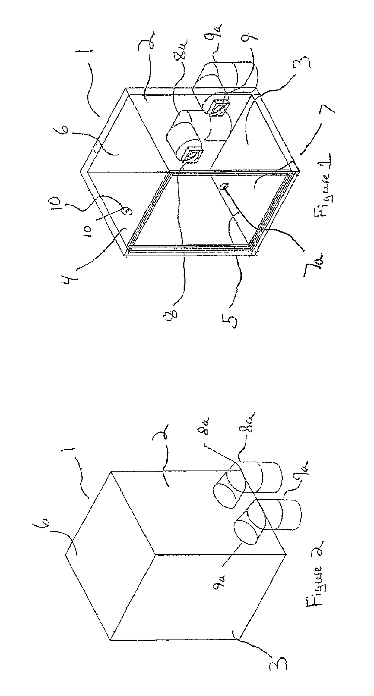
[0025]Examples of the receptacle 1 of the present invention are shown in the attached figures. FIGS. 1-2 show a first embodiment of the receptacle 1 of which FIG. 1 is a front view and FIG. 2 is a rear view. The receptacle has a rear sidewall 2 and a first 3 and second sidewall 4 that are oppositely situated and that extend from the rear sidewall 2 to the front of the receptacle. A bottom wall 5 is positioned at the bottom of the sidewalls and a cover 6 is positioned on the top of the sidewalls. The bottom wall, top wall, and sidewalls combine to form a five walled rectangular receptacle that has an opening in the front for receiving a sealable door 7 that may be hinged to a sidewall of the receptacle by any means known in the art and that further includes a handle portion 7a. The handle portion may have a latch mechanism that enables the door to be locked in a closed position. In addition, the edges of the door 7 and the edges of the walls of the receptacle that contact the door ar...


PUM

PropertyMeasurementUnit
temperaturesaaaaaaaaaa
areaaaaaaaaaaa
storage areaaaaaaaaaaa

Abstract

The present invention relates to a sealed and ventilated receptacle for storing equipment, such as firefighter turnout gear, that generally includes a base, at least one sidewall extending from the base, and a top wall that covers the opposite end of the sidewall. A sealable door may be positioned on the sidewall to access the inside of the receptacle and to prevent any contaminants from exiting the receptacle. The receptacle may also include an intake fan and exhaust fan that are each connected to a duct for providing fresh air to and removing contaminated air from the inside of the receptacle. The receptacle may further include a temperature control unit for regulating the temperature inside of the receptacle. Additionally, a hook for hanging a firefighter coat, trousers, or other items may also be included on the inside of the receptacle.

Description

FIELD OF THE INVENTION[0001]The present invention relates to sealed receptacles that are ventilated for storing equipment. More specifically, the present invention relates to a receptacle for storing firefighter turnout gear or other items that require a sealed and ventilated chamber.BACKGROUND OF THE INVENTION[0002]The term “turnout gear” refers to the system of outer protective clothing that is worn by firefighters before entering a hazardous environment. The turnout gear generally consists of fire resistant boots, fire resistant trousers, fire resistant coat, fire resistant gloves, the firefighter nomex head hood, and the firefighter helmet. Firefighters typically carry their personal turnout gear in their vehicles, such as in the trunk of a sports utility vehicle (“SUV”), so that they will be ready to respond to an emergency. The gear is stored in specially manufactured cabinets that are designed to accommodate the different components of the gear. However, since the turnout gea...

Claims


Application Information

Patent Timeline
Patent Type & Authority Patents(United States)
IPC IPC(8): A62B15/00B08B15/02A61L2/10
CPCA62B15/00B08B15/023A61L2202/14A61L2/10H05K999/99
Inventor SQUICCIARINI, ROBERT
Owner SQUICCIARINI ROBERT
Learn More