
Vehicle instrument device

a technology for vehicle instruments and control circuit boards, which is applied in the field can solve the problems of increasing the cost of vehicle instrument devices, and achieve the effects of reducing costs, preventing excessive quality, and facilitating the design of pointer control circuit boards

Active Publication Date: 2018-05-15
YAZAKI CORP
View PDF5 Cites 0 Cited by
  • Summary
  • Abstract
  • Description
  • Claims
  • Application Information

AI Technical Summary

Benefits of technology

This patent aims to provide a solution for improving the quality and reducing the cost of a vehicle instrument device that includes a pointer-type instrument and a display device arranged alongside each other. The technical effect of the patent is to design a pointer control circuit board that is simple and easy to design, while preventing excessive quality and reducing the cost of the overall instrument device. The configuration of the patent allows for a reduced complexity of the pointer control circuit board, while still achieving a common use of the display device. Additionally, the patent provides a display control circuit board that has an exposed external connector, which makes it easy to connect external circuits. Overall, the patent provides a solution for integrating apointer-type instrument and a display device in a cost-effective and easy-to-design manner.

Problems solved by technology

Therefore, the circuit board becomes excessive in quality with respect to the electronic circuit for the pointer-type instrument, and thus, an increase in the cost of the vehicle instrument device occurs.

Method used


Image

  • Vehicle instrument device
  • Vehicle instrument device
  • Vehicle instrument device

Examples


Embodiment Construction

[0029]Hereinafter, a preferred embodiment of a vehicle instrument device according to the present invention will be described in detail with reference to the drawings.

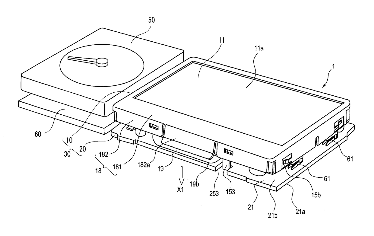
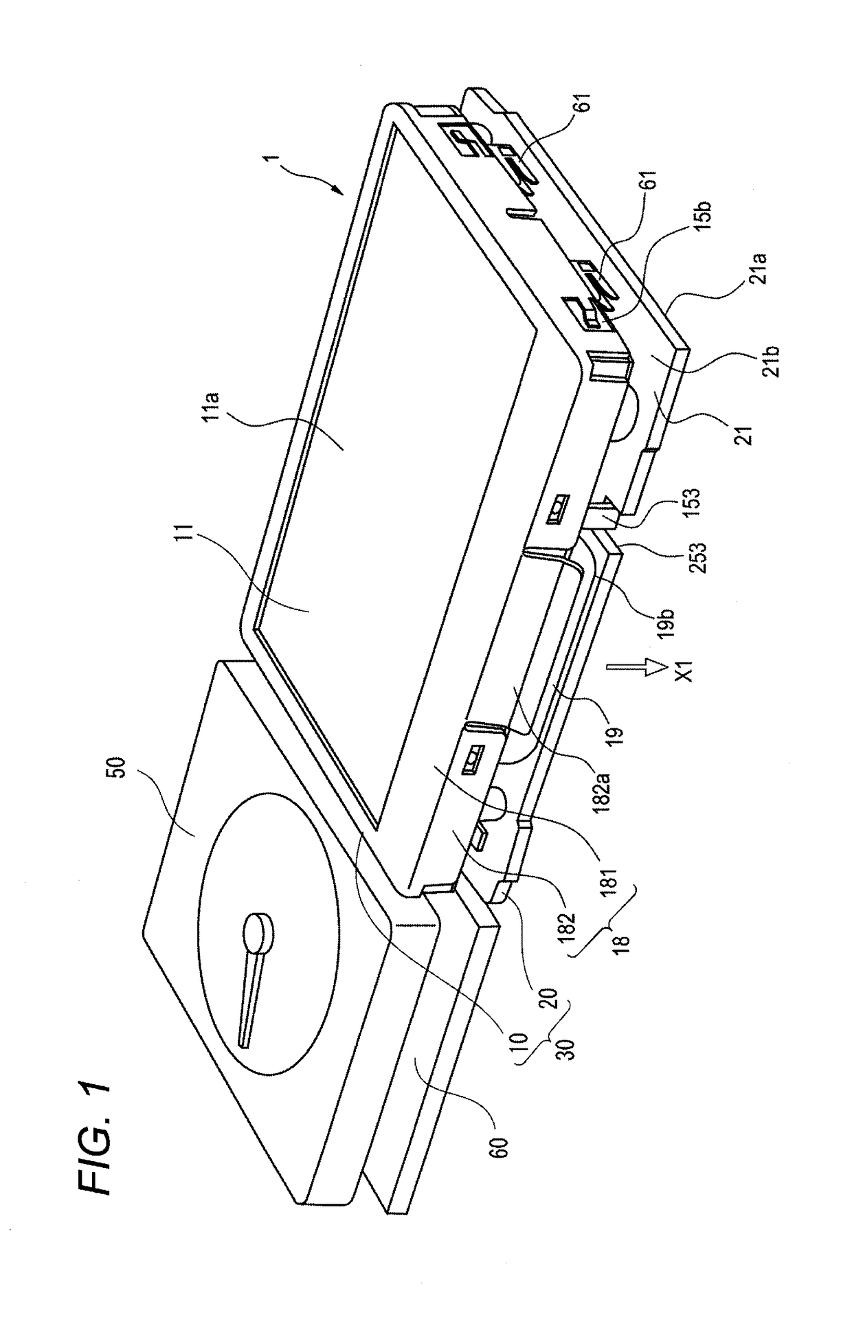
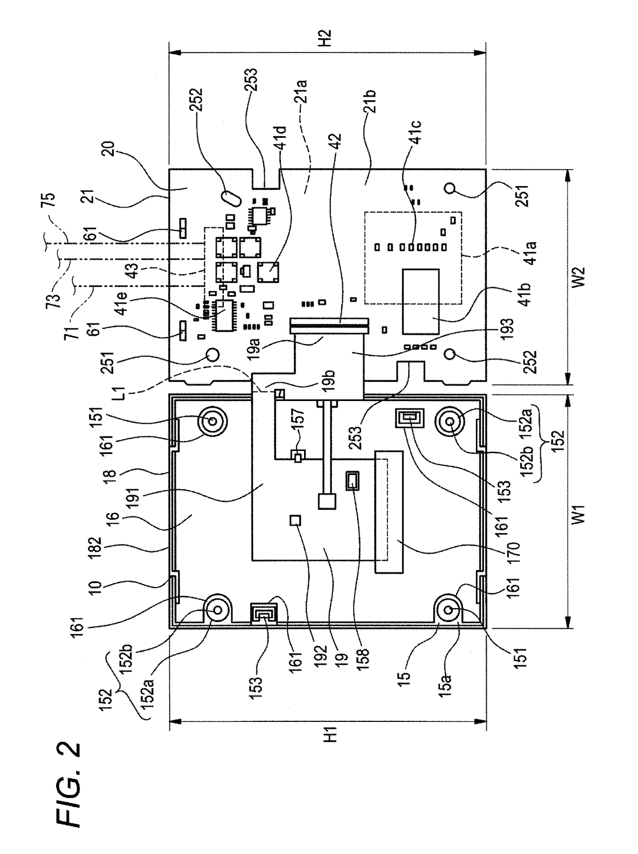
[0030]FIG. 1 is a perspective view of a display unit in an embodiment of a vehicle instrument device according to the present invention, and FIG. 2 is a development view of the display unit shown in FIG. 1.

[0031]A vehicle instrument device 1 of the embodiment is a combination meter which is disposed on the dashboard of a vehicle, and a pointer-type instrument 50 and a liquid crystal display device (display device) 10 are arranged alongside each other in a device housing (not shown).

[0032]For example, the pointer-type instrument 50 includes a speedometer, a tachometer, or the like.

[0033]In the case of the present embodiment, an LCD control circuit board (display control circuit board) 20 is detachably attached to the rear surface of the liquid crystal display device 10 serving as the display device. The LCD control circ...


PUM


Abstract

A vehicle instrument device includes: a display device accommodated in the vehicle instrument device; a display control circuit board which controls an operation of the display device and which is attached to a rear surface of the display device; and an instrument control circuit board which controls display except for the display device and which is formed as a separate member from the display control circuit. The display device, which is integrated with the display control circuit board to serve as a display unit, is accommodated in the vehicle instrument device together with the instrument control circuit board.

Description

CROSS REFERENCE TO RELATED APPLICATION(S)[0001]This application is a continuation of PCT application No. PCT / JP2013 / 083125, which was filed on Dec. 10, 2013 based on Japanese Patent Application (No. 2012-269629) filed on Dec. 10, 2012, the contents of which are incorporated herein by reference.BACKGROUND OF THE INVENTION[0002]1. Field of the Invention[0003]The present invention relates to a vehicle instrument device in which a pointer-type instrument and a display device are arranged alongside each other.[0004]2. Description of the Related Art[0005]FIG. 3 shows a vehicle instrument device described in JP-A-2010-181478 described below.[0006]A vehicle instrument device 100 is a complex meter (combination meter) which is disposed on a dashboard of a vehicle, and has a structure in which a pointer-type instrument (not shown) such as a speedometer or a tachometer and a liquid crystal display device (display device) 120 are arranged alongside each other in a device housing 110.[0007]A dis...

Claims


Application Information

Patent Timeline
Patent Type & Authority Patents(United States)
IPC IPC(8): H04N5/64B60K35/00B60K37/00
CPCB60K35/00B60K37/00B60K2350/1064B60K35/215
Inventor KONDO, KAZUAKI
Owner YAZAKI CORP
Learn More