
Vehicle exhaust system with resonance damping

a technology of resonance damping and exhaust system, which is applied in the direction of engine components, mechanical equipment, machines/engines, etc., can solve the problems of increasing weight, introducing new sources of noise generation, and components that are prone to undesirable noise, so as to reduce the resonance frequency

Inactive Publication Date: 2018-05-15
FAURECIA EMISSIONS CONTROL TECH GERMANY
View PDF63 Cites 15 Cited by
  • Summary
  • Abstract
  • Description
  • Claims
  • Application Information

AI Technical Summary

Benefits of technology

The invention relates to a vehicle exhaust system that includes an exhaust component with a bleed hole to reduce a resonance frequency. The bleed hole has a discontinuous opening into the exhaust component cavity and may be covered by a porous member or a boss. The bleed hole can be positioned at an anti-node position, which is about 25% or 50% of the overall length of the exhaust component. The exhaust component can also include a muffler or a Helmholtz resonator, which includes a housing and the bleed hole is located in the housing or within the end caps. The technical effect of the invention is to improve the exhaust system's performance and reduce noise and resonance frequencies.

Problems solved by technology

The overall system and / or the components are capable of generating undesirable noise as a result of resonating frequencies.
The disadvantage of adding additional components is that it is expensive and increases weight.
Further, adding components introduces new sources for noise generation.
ANC systems can be complex, very expensive, and can take up significant amounts of packaging space.
Further, these systems are not always effective in attenuating wide ranges of resonance frequencies.

Method used


Image

  • Vehicle exhaust system with resonance damping
  • Vehicle exhaust system with resonance damping
  • Vehicle exhaust system with resonance damping

Examples


Embodiment Construction

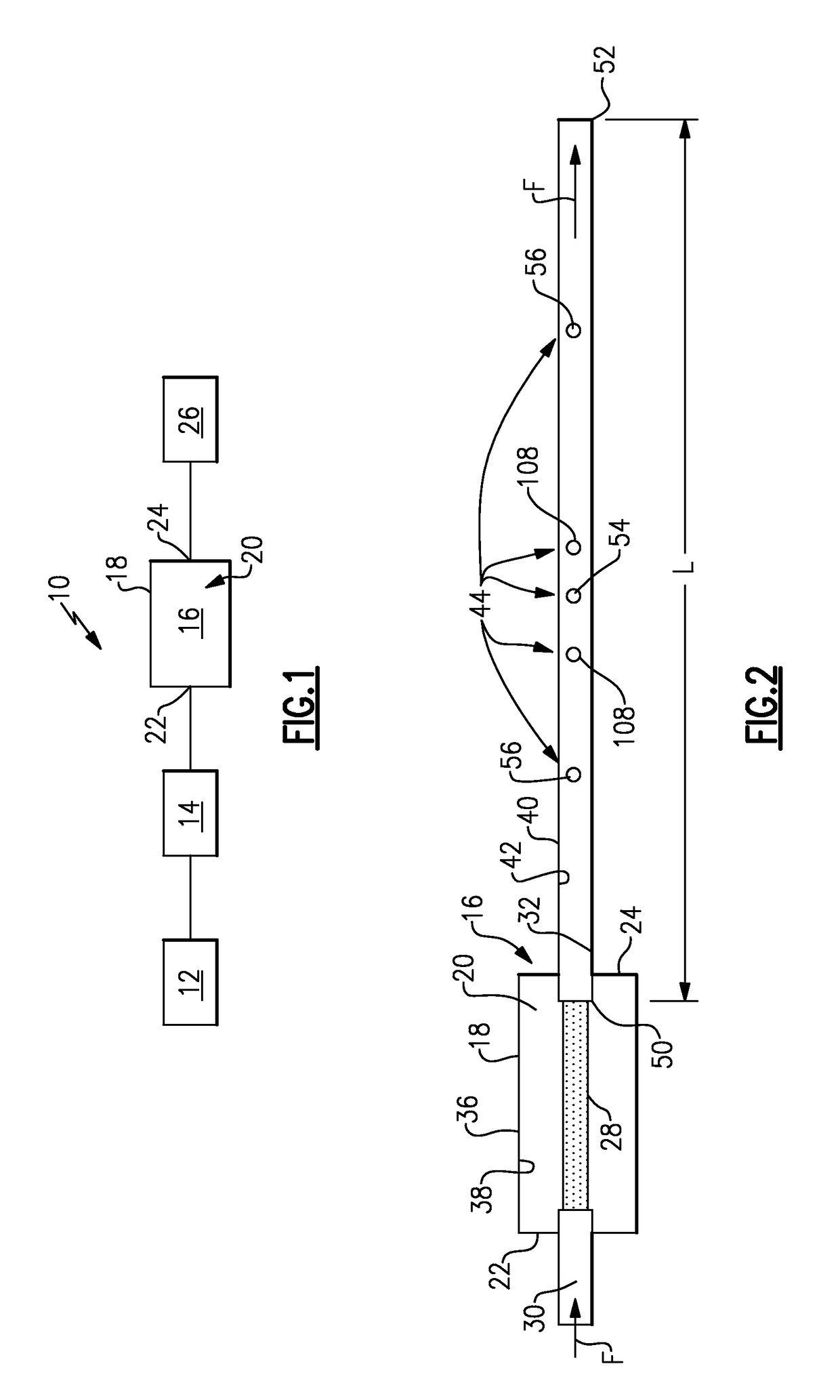
[0033]FIG. 1 shows a vehicle exhaust system 10 that conducts hot exhaust gases generated by an internal combustion engine 12 through exhaust components 14 to reduce emissions and control noise as known. The exhaust system 10 also includes at least one muffler 16 that functions to attenuate exhaust noise. The muffler 16 includes an outer housing 18 that defines an internal cavity 20. The muffler 16 has an inlet end 22 and an outlet end 24. Exhaust gases exits the outlet end 24 and is directed to downstream exhaust components 26, which can include a tailpipe, for example, through which exhaust gases exit to atmosphere.

[0034]The exhaust components 14 and 26 can include diesel oxidation catalysts (DOC), selective catalytic reduction (SCR) catalysts, particulate filters, exhaust pipes, etc. These components 14 can be mounted in various different configurations and combinations dependent upon vehicle application and available packaging space.

[0035]The exhaust system 10 includes various ac...


PUM


Abstract

A vehicle exhaust system includes an exhaust component having an outer surface and an inner surface that defines an internal exhaust component cavity. At least one bleed hole is formed in the exhaust component to reduce a resonance frequency. The bleed hole comprises a discontinuous opening into the exhaust component cavity.

Description

TECHNICAL FIELD[0001]The subject invention relates to a vehicle exhaust system with resonance damping to reduce noise.BACKGROUND OF THE INVENTION[0002]Vehicle exhaust systems direct exhaust gases generated by an internal combustion engine to the external environment. These systems are comprised of various components such as pipes, converters, catalysts, filters, etc. The overall system and / or the components are capable of generating undesirable noise as a result of resonating frequencies. Different approaches have been used to address this issue.[0003]For example, components such as mufflers, resonators, valves, etc., have been incorporated into exhaust systems in an attempt to attenuate certain resonance frequencies generated by the exhaust system. The disadvantage of adding additional components is that it is expensive and increases weight. Further, adding components introduces new sources for noise generation.[0004]Another approach utilizes active noise control (ANC) in an attemp...

Claims


Application Information

Patent Timeline
Patent Type & Authority Patents(United States)
IPC IPC(8): F01N1/02F01N13/08F01N1/08F01N1/00
CPCF01N1/023F01N1/02F01N13/08F01N1/082F01N1/083F01N1/026
Inventor ABRAM, KWINCALLAHAN, JOSEPH E.PHAM, TOMMY
Owner FAURECIA EMISSIONS CONTROL TECH GERMANY
Learn More