
Integral spring-hidden capo

Inactive Publication Date: 2018-05-22
SHENZHEN MUZITECH TECH CO LTD
View PDF35 Cites 2 Cited by
  • Summary
  • Abstract
  • Description
  • Claims
  • Application Information

AI Technical Summary

Benefits of technology

The capo is a new and improved string clamp that overcomes the limitations of existing caps. It can be operated with greater skill, portability, and efficiency. The capo improves stability, aesthetic appearance, and self-adaptive capability, allowing for balanced and conformable clamping of strings on the neck. It has a freely-rotatable rotating wheel and a power component that allows for rotation of the wheel while maintaining stability. The capo has a simple production process and high integrity and appearance quality.

Problems solved by technology

An existing capo has the disadvantages of too simple operation experience, exposure of a spring of a power device, low integrity of a product structure or the like.
In view of the limitation that a spring is very close to a rotating shaft pivot when a clamping body is nipped, most conventional capos have low efficacy of elasticity due to the inconsistence between the direction of acting force of the spring and the clamping direction of the clamping body, but various conventional capos basically have no obvious difference in substantial operation experience.

Method used


Image

  • Integral spring-hidden capo
  • Integral spring-hidden capo
  • Integral spring-hidden capo

Examples


embodiment 1

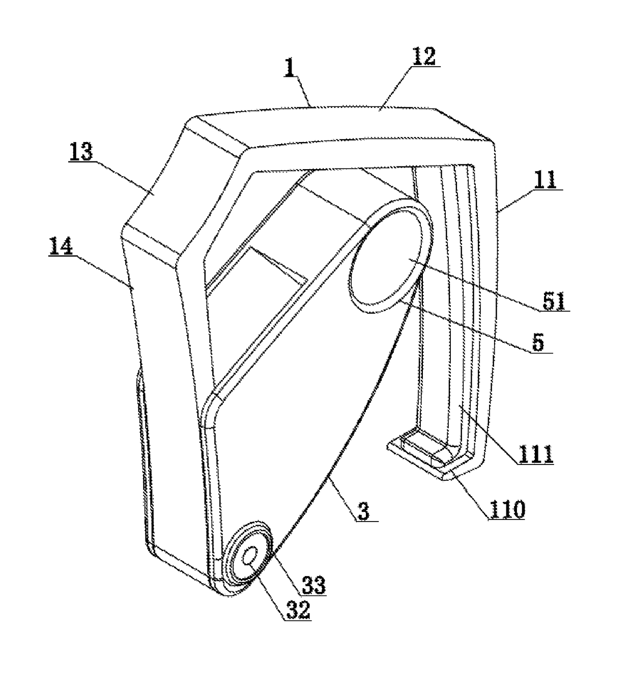
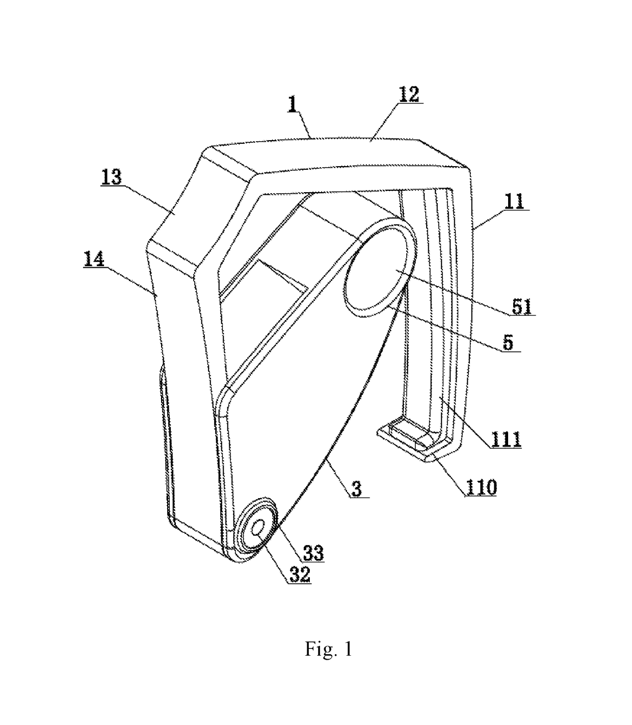
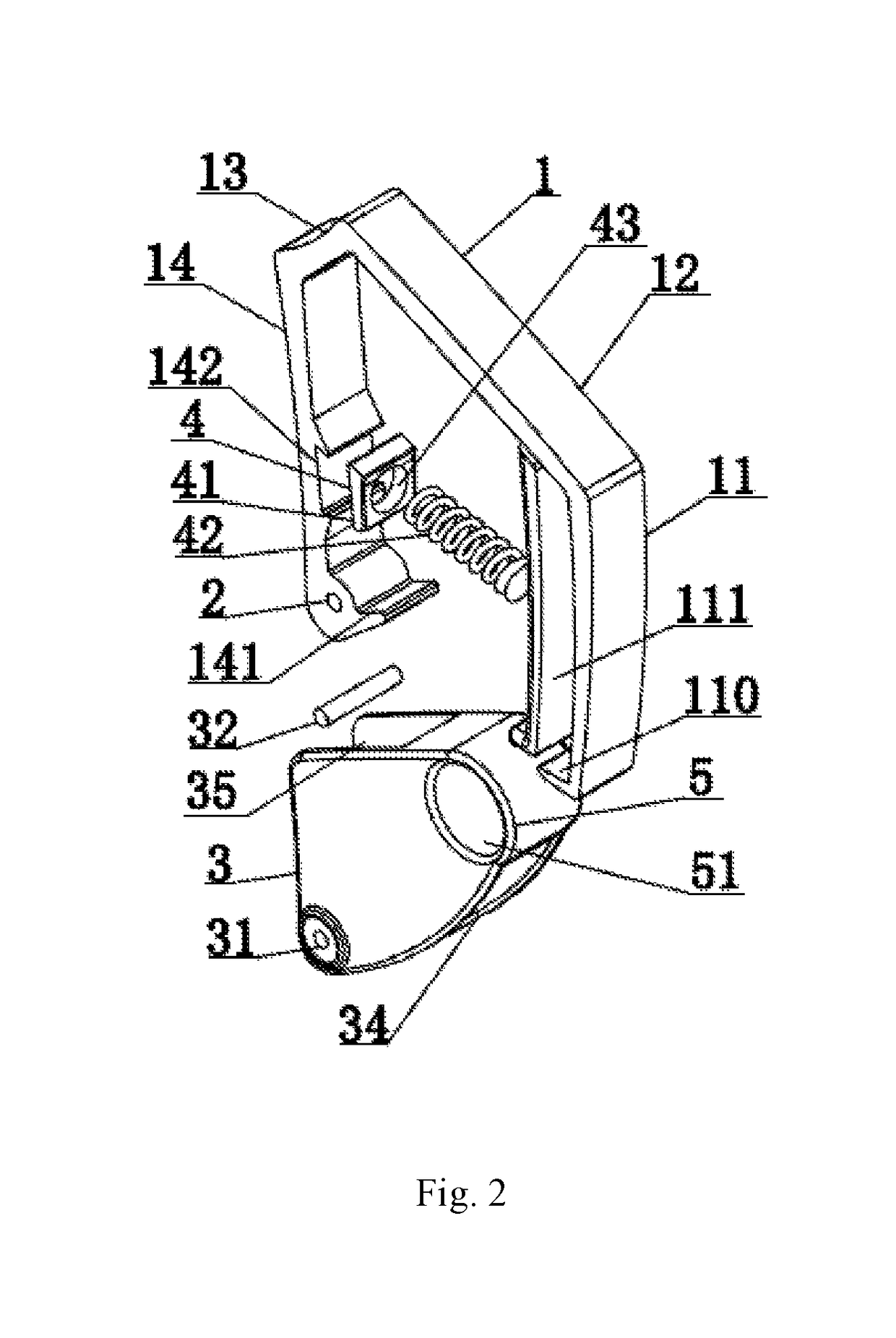
[0034]As shown in FIGS. 1, 2, 3, 4 and 5, an integral spring-hidden capo is configured to tightly press a neck by inverting a rotating shaft and comprises a U-shaped capo skeleton 1, wherein a capo skeleton rotating shaft hole 2 is arranged at an end at an opening of the U-shaped capo skeleton 1, the capo skeleton rotating shaft hole 2 is equipped with an integral push-pull handle component 3, one end of a power unit 4 is located above the capo skeleton rotating shaft hole 2 of the U-shaped capo skeleton 1, the other end of the power unit 4 is hidden inside the integral push-pull handle component 3, and an upper part of the integral push-pull handle component 3 is provided with a finger force-bearing component 5 for allowing the integral push-pull handle component 3 to move upwards along an arc trajectory around the capo skeleton rotating shaft hole 2.

[0035]Preferably, the U-shaped capo skeleton 1 comprises a string-pressing arm 11, a connecting arm 12, a pressing force-bearing arm ...

embodiment 2

[0045]As shown in FIGS. 6, 7, 8 and 9, a rotating wheel mechanism mounting station 6 is arranged between the neck-back pressure wall 34 and a neck-back contact surface, and the rotating wheel mechanism mounting station 6 is internally provided with a rotating wheel mechanism 61; and the rotating wheel mechanism 61 comprises a rotating wheel shaft 610 and a rotating wheel 611, the rotating wheel 611 is sleeved on the rotating wheel shaft 610 and capable of rotating about the rotating wheel shaft 610, an upper part of the rotating wheel 611 is embedded into the rotating wheel mechanism mounting station 6, the rotating wheel shaft 610 is mounted on a mounting seat 62 at both sides of the rotating wheel mechanism mounting station 6, the rotating wheel 611 functions to press against a neck back during operation of the capo, an outer ring of the rotating wheel 611 is sleeved with a soft rubber kit 612, and the soft rubber kit 612 is used for protecting a neck when the rotating wheel 611 c...


PUM


Abstract

The invention provides an integral spring-hidden capo comprising a U-shaped capo skeleton, wherein a capo skeleton rotating shaft hole is arranged at an end at an opening of the U-shaped capo skeleton, the capo skeleton rotating shaft hole is equipped with an integral push-pull handle component, one end of a power unit is located above the capo skeleton rotating shaft hole of the U-shaped capo skeleton, and the other end of the power unit is hidden inside the integral push-pull handle component. The invention has the following beneficial effects: the capo can be stably and portably operated by two fingers, and has high integrity and a simple process.

Description

FIELD OF THE INVENTION[0001]The invention relates to a capo for a stringed instrument, and particularly to an integral spring-hidden capo for instruments such as a guitar and a banjo.BACKGROUND OF THE INVENTION[0002]Conventional capos, especially spring-type capos (mostly spring-exposed capos) need to be gripped and operated by the whole palm, and almost all of such capos are provided with a rotating shaft point at an upper end of a capo for clamping a neck of a musical instrument in terms of structural principles. That is to say, a conventional spring-powered capo is basically of the most original staggered clamping-body structure in nature, i.e. an original staggered clamping-body structure such as a spring is arranged at an outer clamping side of a clamp or the other end of an intersecting shaft. An existing capo has the disadvantages of too simple operation experience, exposure of a spring of a power device, low integrity of a product structure or the like. In view of the limita...

Claims


Application Information

Patent Timeline
IPC IPC(8): G10D3/04
CPCG10D3/043G10D3/147G10D3/053
Inventor LIANG, JIAN
Owner SHENZHEN MUZITECH TECH CO LTD
Learn More