
Logical L3 processing for L2 hardware switches

Active Publication Date: 2018-05-22
NICIRA
View PDF88 Cites 22 Cited by
  • Summary
  • Abstract
  • Description
  • Claims
  • Application Information

AI Technical Summary

Benefits of technology

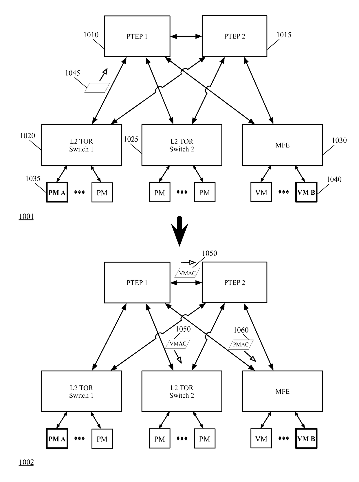
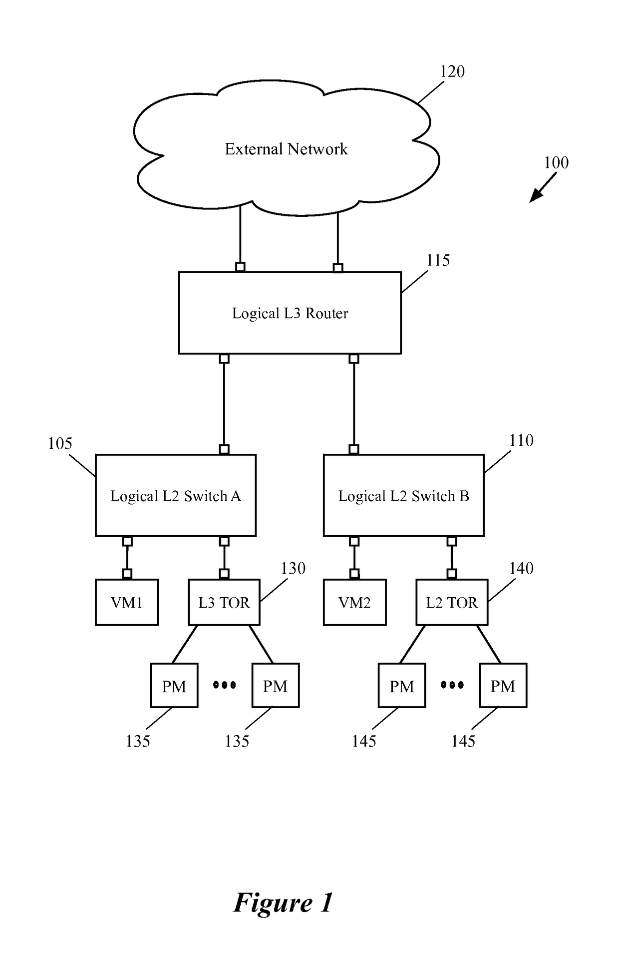
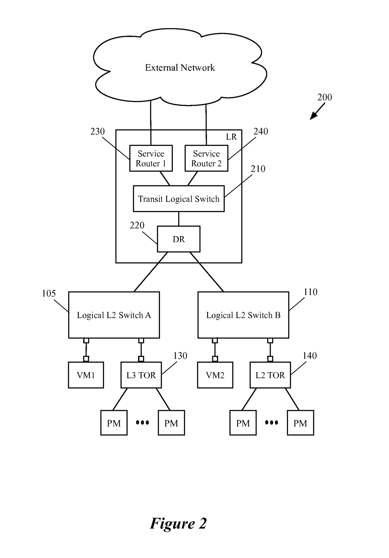
The patent describes a method for integrating logical networks with physical networks in a datacenter. It introduces a control plane that manages logical networks for tenants of the datacenter. The control plane configures logical routers and designates designated transport nodes for handling distributed L3 functions. The designated transport nodes act as intermediate destination tunneling endpoints for distributed L2 hardware switches. The method allows for the efficient routing of network traffic and provides load balancing across different host machines. The control plane also includes a definition of a logical router with several routing components, including a distributed router and service routing components. The distributed routing component performs distributed routing on behalf of the logical router, and the service routing components communicate with external networks through uplink interfaces and a transit logical switch. Overall, the method improves the efficiency and reliability of the datacenter network.

Problems solved by technology

One of the challenges in today's hosting system networks is extending the virtual networks (e.g., of one or more tenants) to other physical networks through hardware switches (e.g., third-party hardware switches) by enabling the hardware switches to implement logical L2 and L3 forwarding elements.

Method used


Image

  • Logical L3 processing for L2 hardware switches
  • Logical L3 processing for L2 hardware switches
  • Logical L3 processing for L2 hardware switches

Examples


Embodiment Construction

[0032]In the following detailed description of the invention, numerous details, examples, and embodiments of the invention are set forth and described. However, it should be understood that the invention is not limited to the embodiments set forth and that the invention may be practiced without some of the specific details and examples discussed.

[0033]Some embodiments provide a novel method for performing logical routing functionalities for a layer 2 (L2) managed hardware forwarding element (MHFE) in order to integrate the physical workload attached to the L2 MHFE (e.g., an L2 third-party hardware switch such as an L2 top-of-rack (TOR) switch) with one or more logical networks. In some embodiments, the method is performed by a control plane that configures and manages one or more logical networks for one or more tenants of a hosting system (e.g., a datacenter). Some embodiments configure one or more logical routers of a logical network on one or more designated transport nodes. A de...


PUM


Abstract

A method for learning a MAC address of an end machine that is logically connected to a logical network is described. The method receives configuration data for implementing a distributed logical router having different logical ports each of which is associated with a logical port of a logical switch. The method receives a packet through a first logical port of the logical router that has a destination IP address associated with a particular logical switch that is associated with a second logical port of the logical router. In order to learn the MAC address of the end machine, the method sends a first broadcast packet with a first source MAC address to a first set of forwarding elements that implements the particular logical switch, and sends a second broadcast packet with a second source MAC address to a second set of forwarding elements that also implements the particular logical switch.

Description

BACKGROUND[0001]There is a growing movement, driven by both industry and academia, towards a new network control paradigm called Software-Defined Networking (SDN). In Software-Defined Networking (SDN), a control plane implements and maintains the control logic that governs the forwarding behavior of shared network switching elements on a per user basis. A virtual network that is implemented for a tenant of a hosting system is a good example of an SDN. The virtual (logical) network of a tenant of the hosting system connects a set of data compute nodes (e.g., virtual machines) that are assigned to the tenant, to each other and to other virtual and / or physical networks through a set of logical switches and logical routers.[0002]One of the challenges in today's hosting system networks is extending the virtual networks (e.g., of one or more tenants) to other physical networks through hardware switches (e.g., third-party hardware switches) by enabling the hardware switches to implement lo...

Claims


Application Information

Patent Timeline
Patent Type & Authority Patents(United States)
IPC IPC(8): H04L12/24H04L12/721
CPCH04L41/0803H04L45/72H04L41/12H04L41/0895
Inventor CHANDA, ANUPAMTHAKKAR, PANKAJ
Owner NICIRA
Learn More