Torque transfer in laterally engaging drive couplers exhibiting axial misalignment with driven couplers

a technology of torque transfer and driven couplers, which is applied in the direction of interengaging clutches, couplings, lighting and heating apparatus, etc., to achieve the effect of reducing axial misalignment and reducing collision impa

Active Publication Date: 2018-05-29
TESLA INC
View PDF33 Cites 2 Cited by
  • Summary
  • Abstract
  • Description
  • Claims
  • Application Information

AI Technical Summary

Benefits of technology

[0012]It is another object of the invention to provide for torque transfer upon lateral engagement between drive and driven couplers belonging to such mobile and stationary units under conditions of axial misalignment between the drive and driven axes. More precisely, it is an objective to provide for transferring torque that can accommodate misalignment of the couplers. The design of the coupler can be such that when torque is transmitted and the couplers are misaligned, components of the contact forces push the couplers back into stable alignment.
[0018]The first and second mating members used by the drive and driven couplers to couple for the torque transmission process are preferably provided with certain structure. For example, they have engagement features designed for urging the members to assume a three-dimensionally constrained relative engagement pose. Preferably, the engagement features not only support coupling with the amount of misalignment due to imperfect first-order coaxial alignment, but even reduce misalignment to a second-order coaxial alignment. The engagement features can be embodied by engagement prongs, pins, protrusions and other geometric features on either member. Preferably, complementary mating features, which can be embodied by recesses, slots or ridges, are provided on the other member to urge the members into the three-dimensionally constrained relative engagement pose that also reduces axial misalignment. The improvement in misalignment to a second-order coaxial alignment is especially important when the first-order coaxial alignment is so poor that it exceeds a predetermined tolerance.
[0019]In some embodiments it is advantageous to provide the drive coupler with one or more collision-mitigating features to mitigate the impact of collisions with the driven coupler that can occur during regular operation. For example, when the apparatus further comprises a rail on which the first unit is mounted and along which it moves between a number of second units, collisions are likely to occur. The second units can be embodied by docking stations or they can be machines fixed at such docking stations to support equipment that requires delivery of torque from the mobile first unit to perform certain operations. The mating members on the driven shafts of the second units can become oriented or re-oriented in unpredictable ways during operation. As a result, the mating member on the drive shaft of the mobile first unit can experience many collisions in moving from one docking station to another.

Problems solved by technology

In this manner, the apparatus is configured to engage and transfer torque between the units whenever required, but typically not on a permanent basis.

Method used


Image

  • Torque transfer in laterally engaging drive couplers exhibiting axial misalignment with driven couplers
  • Torque transfer in laterally engaging drive couplers exhibiting axial misalignment with driven couplers
  • Torque transfer in laterally engaging drive couplers exhibiting axial misalignment with driven couplers

Examples


Embodiment Construction

[0042]The figures and the following descriptions relate to preferred embodiments of the present invention by way of illustration only. It should be noted that alternative embodiments of the structures and methods disclosed herein will be readily recognized as viable options that can be employed without departing from the principles of the claimed invention.

[0043]Reference will now be made to several embodiments of the present invention, examples of which are illustrated in the accompanying figures. Similar or like reference numbers are used to indicate similar or like functionality wherever practicable. The figures depict embodiments of the present invention for purposes of illustration only.

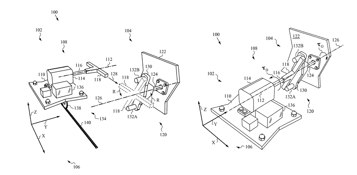
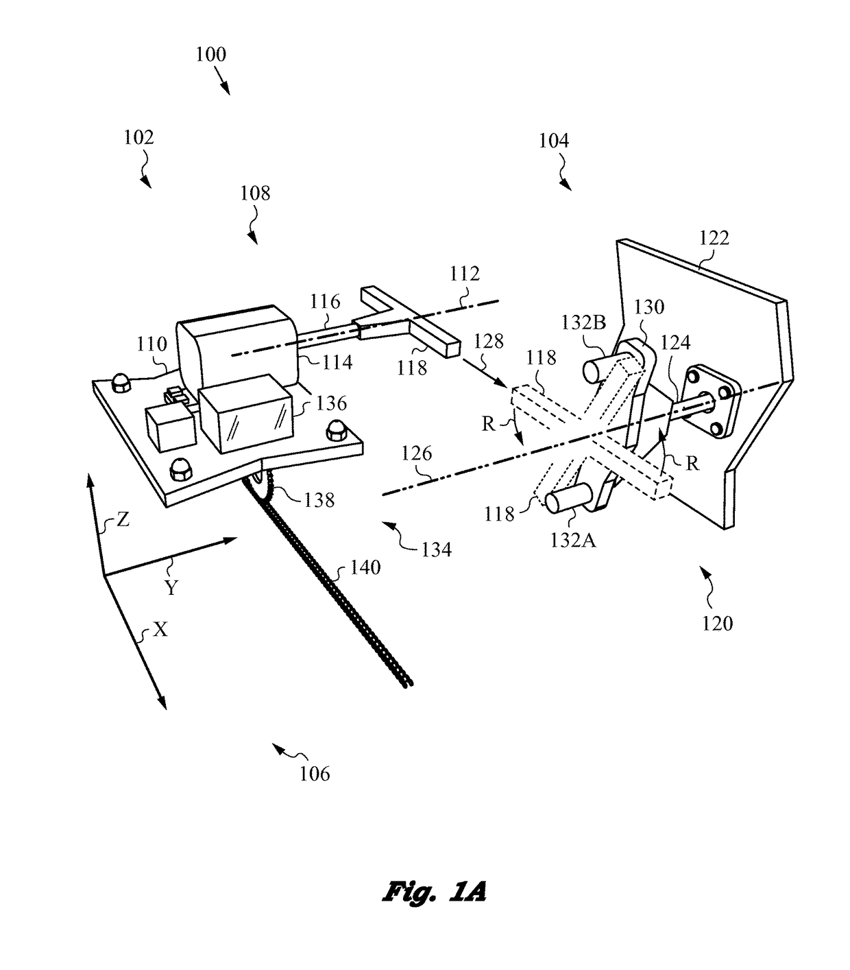
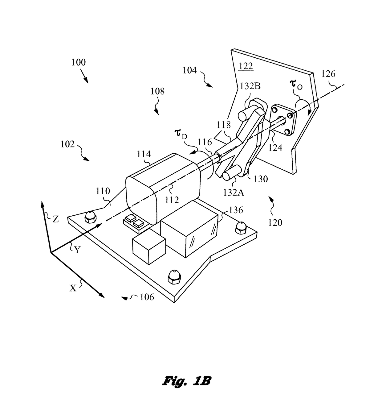
[0044]The present invention will be best understood by first reviewing an apparatus 100 for transferring torque between a first unit 102 and a second unit 104 as shown in the partial perspective view of FIG. 1A. First unit 102 is a mobile machine only partially shown in the drawing figure. Secon...


PUM


Abstract

The present invention relates to transferring torque between a first unit, which is typically a mobile machine or a robot, and a second unit, which is typically a fixed or stationary machine. The units are arranged such that a drive coupler of the first unit designed for delivering torque about a drive axis can engage the driven coupler, which belongs to the second unit and has a driven axis, along an engagement direction that is nearly perpendicular to the direction of the driven axis. A lateral displacement mechanism in provided is the first unit to achieve a first-order coaxial alignment between the drive and driven axes. Additional measures such as compliance mechanisms are provided for improving engagement, coupling and reducing the level of axial misalignment in the apparatus and methods of the invention.

Description

FIELD OF THE INVENTION[0001]This application is related to apparatus and methods of torque transfer between machines whose drive and driven couplers engage laterally or along a direction that is substantially orthogonal or perpendicular to the driven axis of the driven coupler, and more precisely to torque transfer in the presence of a certain amount of axial misalignment between the drive and driven axes of the drive and driven couplers, respectively.BACKGROUND ART[0002]There are numerous mechanisms, including well-known clutch systems that are specifically designed for transmitting torque between machines. Many of these mechanisms and clutch systems have parts that engage, disengage and transmit torque. For various reasons, including the need for reliable transmission of torque at different angular velocities, the prior mechanisms attempt to fix and preserve axial alignment between the machines. Typically, machines achieve this by providing for mechanical engagement between the ma...

Claims


Application Information

Patent Timeline
Patent Type & Authority Patents(United States)
IPC IPC(8): F16D11/16F16D3/04B25J5/02F16D3/10
CPCF16D11/16B25J5/02F16D3/04F16D3/10F24S50/20Y10S901/01Y10S901/30Y10T74/19614Y02E10/47
Inventor FUKUBA, DANIEL I.SUMERS, BENJAMIN D.DITTMER, JEREMY P.JENKINS, MERRITT J.CHU, KEVIN C.RUIZ, VAYARDO L.
Owner TESLA INC
Why Eureka
Try Eureka