Light-based radar system for augmented reality

a technology of light-based radar and augmented reality, applied in the field of data processing, can solve the problem of slow response time of structured-light technology, and achieve the effect of streamlining the disclosur

Active Publication Date: 2018-05-29
META PLATFORMS TECH LLC
View PDF20 Cites 4 Cited by
  • Summary
  • Abstract
  • Description
  • Claims
  • Application Information

AI Technical Summary

Problems solved by technology

However, the response time using structured-light technology can be slow.

Method used


Image

  • Light-based radar system for augmented reality
  • Light-based radar system for augmented reality
  • Light-based radar system for augmented reality

Examples


Embodiment Construction

[0020]Example methods and systems are directed to a light-based radar system for augmented reality. Examples merely typify possible variations. Unless explicitly stated otherwise, components and functions are optional and may be combined or subdivided, and operations may vary in sequence or be combined or subdivided. In the following description, for purposes of explanation, numerous specific details are set forth to provide a thorough understanding of example embodiments. It will be evident to one skilled in the art, however, that the present subject matter may be practiced without these specific details.

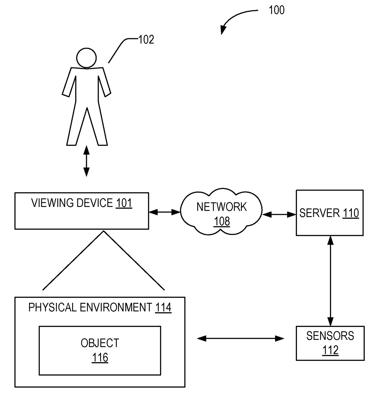
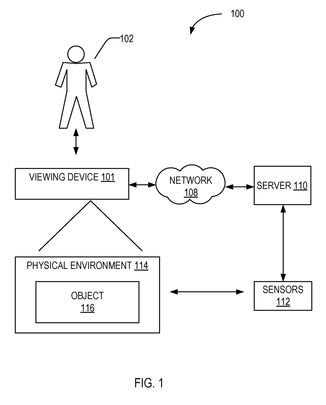
[0021]AR applications allow a user to experience information, such as in the form of a virtual object such as a three-dimensional virtual object overlaid on an image of a physical object captured with a camera of a device. The device may include a smartphone, a tablet, a wearable device or head mounted device such as eyeglasses or a helmet having optical sensors and a display. The ...


PUM


Abstract

A system and method for measuring depth using an optical radar system are described. The system includes an optical radar, a camera, a display, and a processor. The optical radar emits a signal towards an object. The processor identifies an object depicted in an image captured with the camera. The processor generates the signal with a non-repeating pattern of amplitude and frequency, and computes a depth of the object based on a difference in phase angle between the signal emitted from the optical radar and a return signal received at the optical radar. The depth includes a distance between the optical radar and the object. The processor generates AR content based on the identified object and adjusts a characteristic of the AR content in the display based on the computed depth of the object.

Description

REFERENCE TO RELATED APPLICATION[0001]This application claims the benefit of priority of U.S. Provisional Application No. 62 / 164,276 filed May 20, 2015, which is herein incorporated by reference in its entirety.TECHNICAL FIELD[0002]The subject matter disclosed herein generally relates to the processing of data. Specifically, the present disclosure addresses systems and methods for measuring depth using a light-based radar for augmented reality.BACKGROUND[0003]A device can be used to generate and display data in addition to an image captured with the device. For example, augmented reality (AR) is a live, direct or indirect view of a physical, real-world environment whose elements are augmented by computer-generated sensory input such as sound, video, graphics or GPS data. With the help of advanced AR technology (e.g., adding computer vision and object recognition) the information about the surrounding real world of the user becomes interactive. Device-generated (e.g., artificial) inf...

Claims


Application Information

Patent Timeline
Patent Type & Authority Patents(United States)
IPC IPC(8): G09G5/00G06T19/20G06T7/521G01S17/36G01S17/89G06T19/00G02B27/01
CPCG06T19/006G01S17/36G01S17/89G02B27/017G06T7/521G06T19/20G06T2219/2016G02B2027/014G02B2027/0138G06T2207/10152G06T2215/16G06T2219/2012
Inventor MULLINS, BRIANKAMMERAIT, MATTHEWSARARU, MARK ANTHONY
Owner META PLATFORMS TECH LLC
Why Eureka
Try Eureka