Wear resistant low friction coefficient surfaces for joint and bone replacement materials and devices

a low friction coefficient, joint and bone replacement technology, applied in the field of wear resistance low friction coefficient surfaces for joint and bone replacement materials and devices, can solve the problems of high cost, high production cost, and rare practice of patient matched or low volume implants, so as to minimize the friction coefficient and resultant wear, minimize the effect of metal ion release during use and minimize the impact of wear

Inactive Publication Date: 2018-06-05
WASHINGTON STATE UNIVERSITY
View PDF6 Cites 0 Cited by
  • Summary
  • Abstract
  • Description
  • Claims
  • Application Information

AI Technical Summary

Benefits of technology

[0008]The invention relates to lubrication of a metal matrix by addition of biocompatible softer materials, such as at least one solid lubricant, and a method for lubricating and producing the same. The soft material, such as a dry or solid lubricant, embedded into the device minimizes the friction coefficient and resultant wear at the articulating surface of the lubricated metal device. The biocompatible lubricated metal device is made of materials compatible for in vivo and ex vivo applications in order to minimize wear induced degradation and to minimize metal ion release during use. The biocompatible lubricated metal device is suited for use as medical implants, as well as in industrial and other applications, and offers safe composite properties, including biodegradable wear debris in vivo.

Problems solved by technology

These operations require expensive tooling and only make sense for large volume production.
Using similar practice, manufacturing of patient matched or low volume implants become a cost intensive effort and are rarely practiced.
Other challenges such as difficulty in machining of titanium alloys due to high strength, low ductile yield make it even more expensive to machine titanium (Ti) based implants commercially.
In addition, conventional manufacturing technologies are energy intensive, produce significant amounts of materials waste and cannot produce devices with functional gradation.
Since a device such as an artificial joint must undergo a great number of cycles of wear during the lifetime of the host patient, such devices must also possess great fatigue properties.

Method used


Image

  • Wear resistant low friction coefficient surfaces for joint and bone replacement materials and devices
  • Wear resistant low friction coefficient surfaces for joint and bone replacement materials and devices
  • Wear resistant low friction coefficient surfaces for joint and bone replacement materials and devices

Examples


Embodiment Construction

[0019]It is understood that specific embodiments are provided as examples to teach the broader inventive concept, and one of ordinary skill in the art can easily apply the teachings of the present disclosure to other methods and systems. Also, it is understood that the methods and systems discussed in the present disclosure include some conventional structures and / or steps. Since these structures and steps are well known in the art, they will only be discussed in a general level of detail. Furthermore, reference numbers are repeated throughout the drawings for the sake of convenience and example, and such repetition does not indicate any required combination of features or steps throughout the drawings.

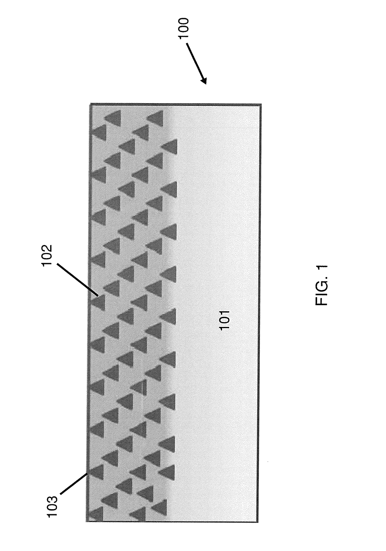
[0020]FIG. 1 illustrates a cross-sectional view of an exemplary lubricated biocompatible metal device 100 according to the present invention. The lubricated metal device 100 may be a solid lubricant 102 embedded into a metal matrix 101 in order to increase hardness and improve wear re...


PUM

PropertyMeasurementUnit
frequencyaaaaaaaaaa
particle sizeaaaaaaaaaa

Abstract

A metal matrix has a biocompatible solid lubricant in at least a portion of its surface and the solid lubricant functions to protect the interior of the metal matrix and minimize the friction coefficient and related wear induced damage at the articulating surface of the metal device. The lubricated biocompatible metal device is made of materials compatible for in vivo and ex vivo applications in order to minimize wear induced degradation as well as metal ion release. The lubricated biocompatible metal device is suited for use as medical implants.

Description

BACKGROUND OF THE INVENTION[0001]The advancement of enhanced materials for the use of medical implants, such as joint prostheses, has immensely improved the quality of life for many people over the past century. Devices such as artificial hips, knees, shoulders and other devices have allowed people who would otherwise have suffered from chronic pain and physical limitation to live active, comfortable lives. The development of such devices has confronted scientists and engineers with many technical challenges, such as in the area of materials science engineering, where various biocompatible materials with different physical and mechanical properties are bonded to each other in order to achieve optimal implant performance.[0002]However, over the past several decades, surgical implants have been manufactured by making a near-net-shape part by forging or casting followed by machining and finishing operations for the desired surface. These operations require expensive tooling and only ma...

Claims


Application Information

Patent Timeline
Patent Type & Authority Patents(United States)
IPC IPC(8): A61L31/14A61F2/30A61L31/02A61L27/04A61L27/06A61L27/32A61L27/50
CPCA61L31/14A61F2/30A61F2/3094A61F2/30767A61L27/04A61L27/06A61L27/50A61L31/022A61L27/32A61L2400/10A61F2002/3097A61F2002/30673A61F2002/30934
Inventor BOSE, SUSMITABANDYOPADHYAY, AMIT
Owner WASHINGTON STATE UNIVERSITY
Why Eureka
Try Eureka