Fan nozzle

a fan nozzle and nozzle technology, applied in the field of nozzles, can solve the problems of creating wear points at the transition, all have a common drawback, and turbulence and wear, and achieve the effects of reducing hot spots in the media flow outlet, reducing turbulence and wear, and improving the performance of the fan nozzl

Inactive Publication Date: 2014-04-10
NGUYEN PHUONG TAYLOR
View PDF13 Cites 0 Cited by
  • Summary
  • Abstract
  • Description
  • Claims
  • Application Information

AI Technical Summary

Benefits of technology

[0016]By providing the transition zone in. accordance with the subject invention the media flow is converted from a flow of circular cross-section to a flow of rectangular cross-section over a longitudinal path. This provides a smooth transition and minimizes both the turbulence and wear. In addition, by providing a smooth transition, the abrasive particles are more evenly distributed throughout the flow area cross-section whereby the hot spots in the media flow outlet are substantially reduced.
[0017]The transition zone is used in combination with a convergence zone to both convert the cross-sectional pattern of the flow and accelerate the flow to provide improved fan nozzle performance with a desirable wide, flat: path with a minimum of hot spots. This permits more even flow of the media and more even cleaning or preparation of the surface being treated.

Problems solved by technology

While such nozzles may be useful for the intended purpose of providing a pressurized blast media in a flat path for cleaning surfaces, they all have a common drawback.
This creates wear points at the transition, as well as turbulence.
In addition, such a configuration creates hotspots in the media flow as the media is released from the nozzle.
This provides for an immediate transition from a circular source to a rectangular nozzle pathway, creating a wear point at the transition as well as generating turbulence in the blow.
While an improvement over earlier designs, this still does not overcome the hot spots typically present in a fan nozzle.

Method used


Image

  • Fan nozzle
  • Fan nozzle
  • Fan nozzle

Examples


Embodiment Construction

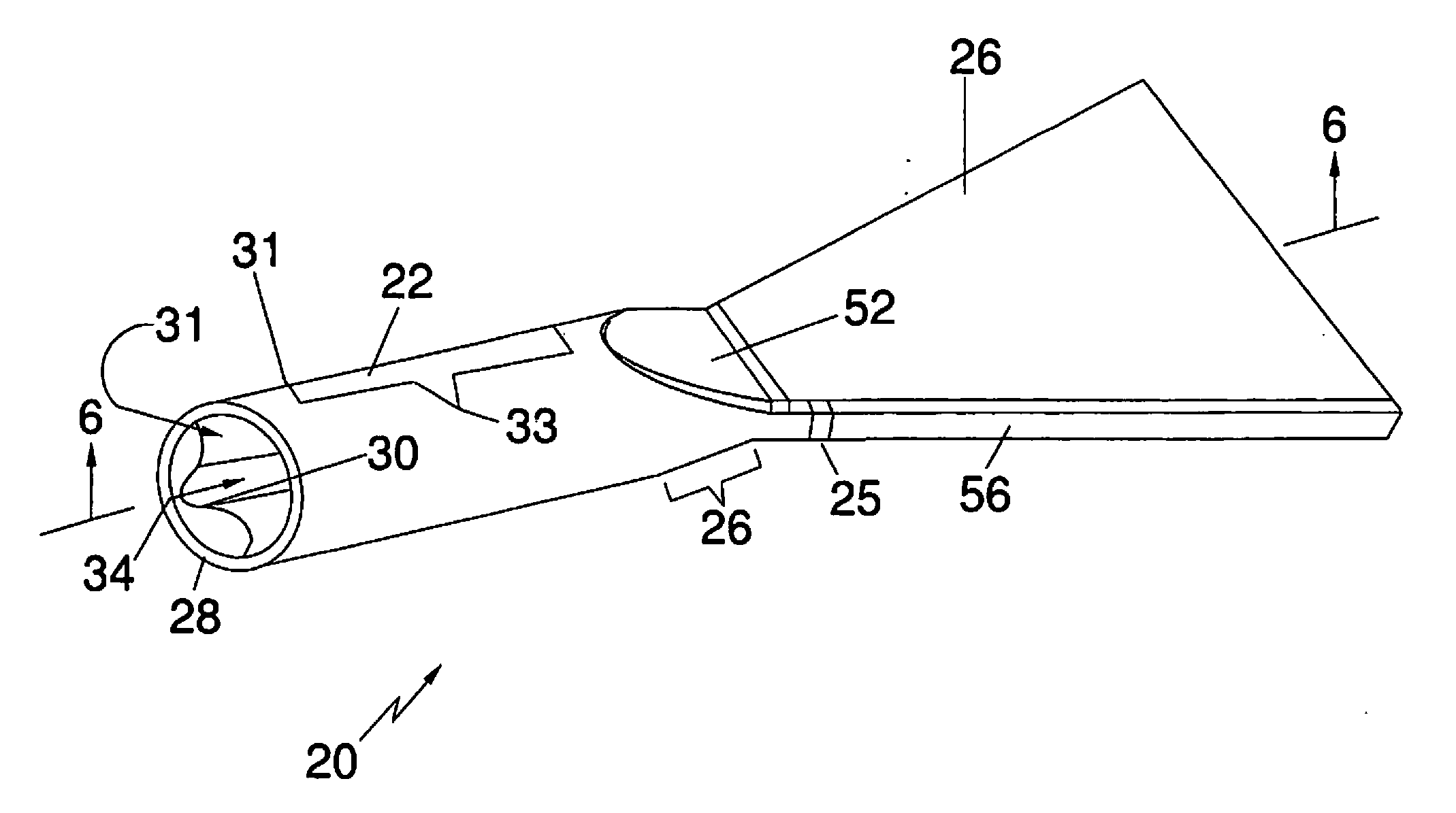
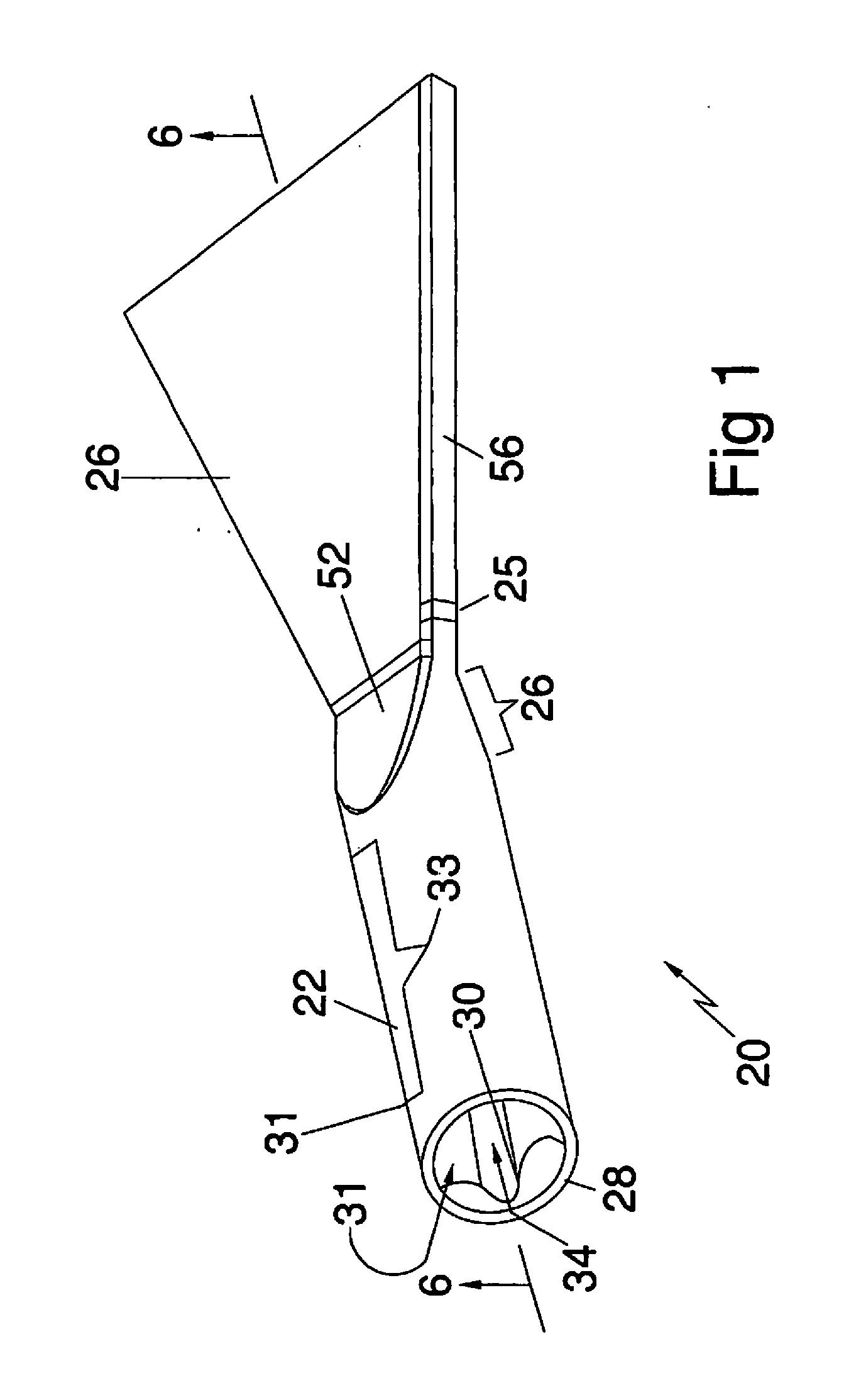
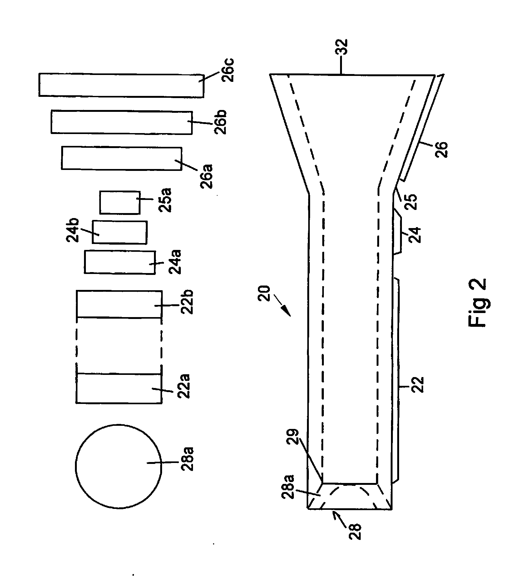
[0031]With specific reference to FIG. 1, the fan nozzle of the subject invention comprises a longitudinal body 20. The fan nozzle is divided into three main sections, the inlet section 22, the transition section 24 and the expansion section 26. A cross-sectional view of the nozzle, taken along line 6-6 of FIG. 1 is shown in FIG. 6. The inlet 28 of the nozzle is adapted to be coupled to a source of pressurized media and is typically of a generally circular cross-section, but may be modified, as at 30, to receive a connector on the source (not shown). Inwardly of the inlet 28, the inlet section 22 is of a rectangular cross-section, as shown in FIGS. 2-5, for distributing the pressurized air or other fluid and the abrasive throughout the full cross-sectional area of the nozzle. Specifically, the inlet end 28 of the nozzle provides a transition from the circular connector at 28a to a rectangular cross-section at 31, with the remainder 33 of the inlet section being of rectangular cross-s...


PUM


Abstract

A fan nozzle for cleaning a surface with an abrasive blast media is constructed of a longitudinal body having an axial pathway through which the media is passed under pressure for release from a substantially rectangular cross-sectional outlet to release the media in a substantially flat, wide path. A first transition zone provides a conversion in the axial pathway from the inlet cross-section to the substantially rectangular cross-section of the outlet opening. A second transition or convergence zone first reduces and then expands the cross-section of the axial pathway for providing a Venturii acceleration of the media as it passes through the nozzle. The transition zone and the convergence zone may be coexistent along a portion of the axial pathway.

Description

CROSS REFERENCE TO RELATED APPLICATION[0001]This application is a continuation of applications U.S. Ser. No. 12 / 012,419 and U.S. Ser. No. 12 / 711,920 for Fan Nozzle, filed on Feb. 1, 2008 and Feb. 24, 2010, respectively. These prior applications are incorporated by reference herein and priority is claimed.BACKGROUND OF THE INVENTION[0002]1. Field of the Invention[0003]The subject invention relates generally to nozzles for releasing abrasive filedia under pressure and is specifically directed to a fan nozzle for releasing the abrasive media in a wide, flat path.[0004]2. Discussion of the Prior Art[0005]Fan nozzles are relatively well known in the industry and are used to release an abrasive media under pressure in a substantially wide, flat path instead of in a circular pattern as with nozzles with round openings. Such nozzles are particularly convenient when the abrasive media is being used to clean a large surface and it is desirable to pass the nozzle over the surface in sweeping m...

Claims


Application Information

Patent Timeline
Patent Type & Authority Applications(United States)
IPC IPC(8): B24C5/04
CPCB24C5/04
Inventor NGUYEN, PHUONG TAYLOR
Owner NGUYEN PHUONG TAYLOR
Why Eureka
Try Eureka