Fan nozzle

Inactive Publication Date: 2017-04-27
NGUYEN PHUONG TAYLOR
View PDF0 Cites 3 Cited by
  • Summary
  • Abstract
  • Description
  • Claims
  • Application Information

AI Technical Summary

Benefits of technology

The patent describes the use of a transition zone to improve the performance of fan nozzles. The transition zone converts the flow from circular to rectangular cross-section, resulting in a smoother transition and reduced turbulence and wear. It also helps to evenly distribute abrasive particles, reducing hot spots at the outlet. By combining the transition zone with a convergence zone, which accelerates the flow and converts its cross-sectional pattern, the fan nozzle achieves improved performance with a desirable wide, flat path. This permits more even flow and cleaning of surfaces.

Problems solved by technology

While such nozzles may be useful for the intended purpose of providing a pressurized blast media in a flat path for cleaning surfaces, they all have a common drawback.
This creates wear points at the transition, as well as turbulence.
In addition, such a configuration creates hotspots in the media flow as the media is released from the nozzle.
This provides for an immediate transition from a circular source to a rectangular nozzle pathway, creating a wear point at the transition as well as generating turbulence in the blow.
While an improvement over earlier designs, this still does not overcome the hot spots typically present in a fan nozzle.

Method used


Image

  • Fan nozzle
  • Fan nozzle
  • Fan nozzle

Examples


Embodiment Construction

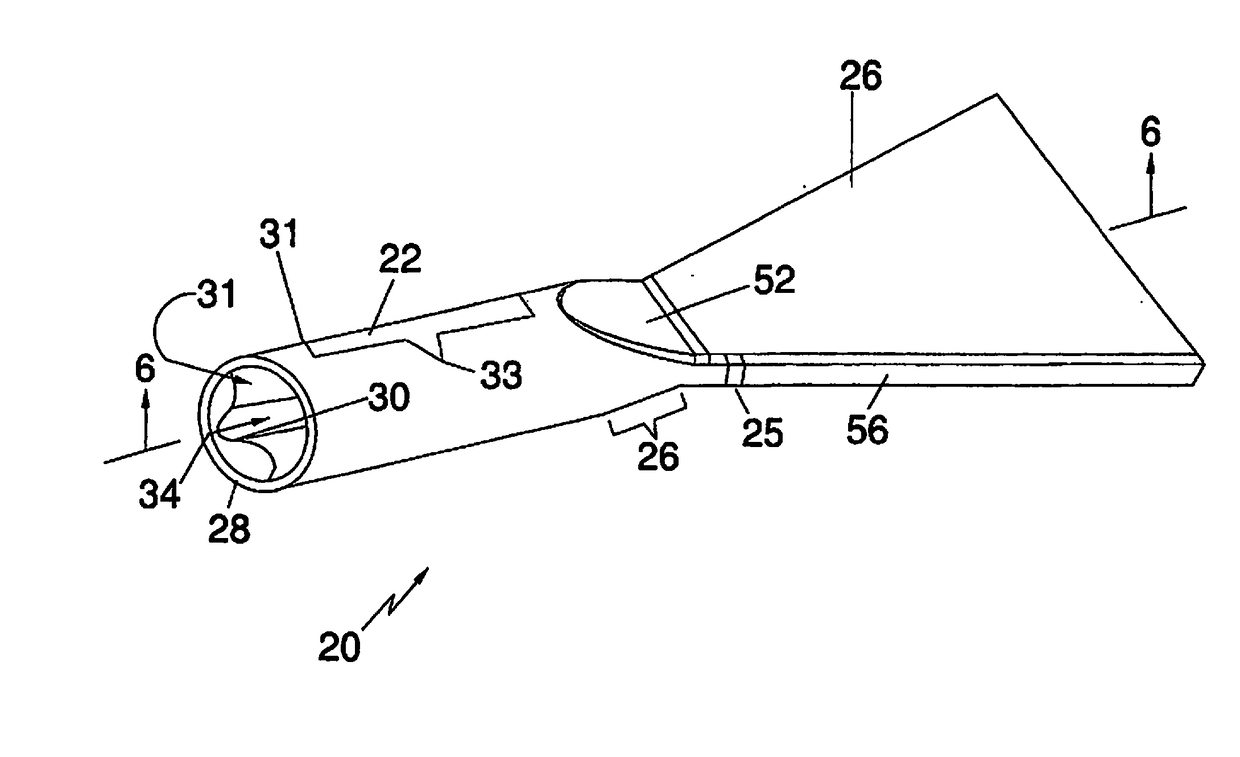
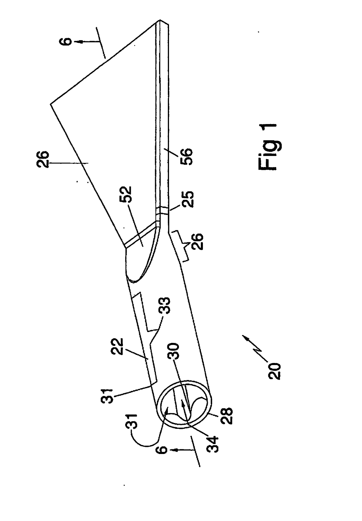
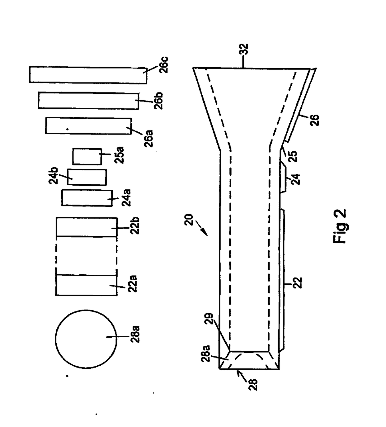
[0031]With specific reference to FIG. 1, the fan nozzle of the subject invention comprises a longitudinal body 20. The fan nozzle is divided into three main sections, the inlet section 22, the transition section 24 and the expansion section 26. A cross-sectional view of the nozzle, taken along line 6-6 of FIG. 1 is shown in FIG. 6. The inlet 28 of the nozzle is adapted to be coupled to a source of pressurized media and is typically of a generally circular cross-section, but may be modified, as at 30, to receive a connector on the source (not shown). Inwardly of the inlet 28, the inlet section 22 is of a rectangular cross-section, as shown in FIGS. 2-5, for distributing the pressurized air or other fluid and the abrasive throughout the full cross-sectional area of the nozzle. Specifically, the inlet end 28 of the nozzle provides a transition from the circular connector at 28a to a rectangular cross-section at 31, with the remainder 33 of the inlet section being of rectangular cross-s...


PUM


Abstract

A fan nozzle for cleaning a surface with an abrasive blast media is constructed of a longitudinal body having an axial pathway through which the media is passed under pressure for release from a substantially rectangular cross-sectional outlet to release the media in a substantially flat, wide path. A first transition zone provides a conversion in the axial pathway from the inlet cross-section to the substantially rectangular cross-section of the outlet opening. A second transition or convergence zone first reduces and then expands the cross-section of the axial pathway for providing a Venturii acceleration of the media as it passes through the nozzle. The transition zone and the convergence zone may be coexistent along a portion of the axial pathway.

Description

CROSS REFERENCE TO RELATED APPLICATION[0001]This application is a continuation of applications U.S. Ser. No. 12 / 012,419 and U.S. Ser. No. 12 / 711,920 for Fan Nozzle, filed on Feb. 1, 2008 and Feb. 24, 2010, respectively. These prior applications are incorporated by reference herein and priority is claimed.BACKGROUND OF THE INVENTION[0002]Field of the Invention[0003]The subject invention relates generally to nozzles for releasing abrasive filedia under pressure and is specifically directed to a fan nozzle for releasing the abrasive media in a wide, flat path.[0004]Discussion of the Prior Art[0005]Fan nozzles are relatively well known in “the industry and are used to release an abrasive media under pressure in a substantially wide, flat path instead of in a circular pattern as with nozzles with round openings. Such nozzles are particularly convenient when the abrasive media is being used to clean a large surface and it is desirable to pass the nozzle over the surface in sweeping motion...

Claims


Application Information

Patent Timeline
IPC IPC(8): B24C5/04B05B1/04
CPCB05B1/044B24C5/04B05B7/1486
Inventor NGUYEN, PHUONG TAYLOR
Owner NGUYEN PHUONG TAYLOR
Why Eureka
Try Eureka