Vehicle body front structure

a front structure and vehicle technology, applied in the direction of bumpers, vehicle arrangements, transportation and packaging, etc., can solve the problems of collision load transfer from the bumper beam extension to the front outer panel, and achieve the effect of absorbing collision energy, increasing joining rigidity, and increasing the amount of collision load transfer

Active Publication Date: 2018-06-05
HONDA MOTOR CO LTD
View PDF6 Cites 2 Cited by
  • Summary
  • Abstract
  • Description
  • Claims
  • Application Information

AI Technical Summary

Benefits of technology

[0012]As described above, the left and right side outer panels are formed from the left and right rear outer panels and the left and right front outer panels. The vertical plate-like left and right side plates of the left and right front outer panels extend from the front ends of the left and right rear outer panels to the front side while inclining outward in the vehicle width direction. The front ends of the left and right side plates are joined to the left and right frame side mounting members provided at the front ends of the left and right front side frames. Thus, the left and right frame side mounting members, the left and right front outer panels, and the left and right side inner panels form left and right gusset structures having a triangular shape in a planar view. The left and right gusset structures project outward in the vehicle width direction from the front ends of the left and right front side frames. When a narrow offset collision occurs in the front part of the vehicle body, the gusset structures can receive a collision load. The collision load is transferred from the gusset structures to the rear half portions of the front side frames. The gusset structures and the front side frames can sufficiently absorb collision energy.
[0034]According to the present invention, it is possible to absorb the collision energy of a narrow offset collision when the narrow offset collision occurs in the front part of a vehicle body while suppressing the weight of the vehicle body and reducing the cost of the vehicle body.

Problems solved by technology

When a narrow offset collision occurs in the front part of the vehicle body, the gusset structures can receive a collision load.

Method used


Image

  • Vehicle body front structure
  • Vehicle body front structure
  • Vehicle body front structure

Examples


Embodiment Construction

[0049]An embodiment of the present invention will be described below with reference to the accompanying drawings.

[0050]A vehicle body front structure according to the embodiment will be described with reference to the accompanying drawings. Note that “front”, “rear”, “left”, “right”, “upper”, and “lower” represent directions viewed from a driver, and Fr, Rr, Le, and Ri indicate the front, rear, left, and right sides, respectively.

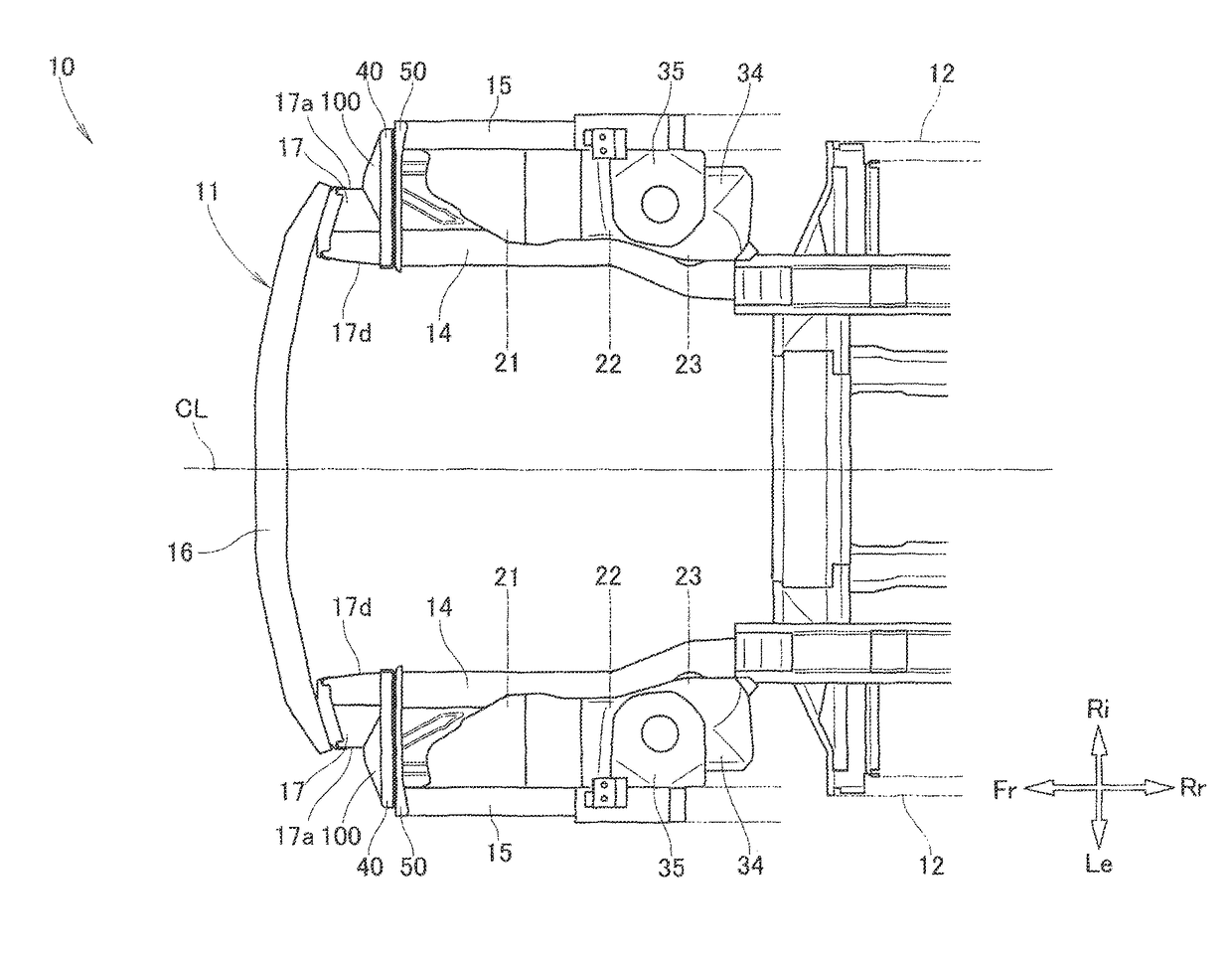
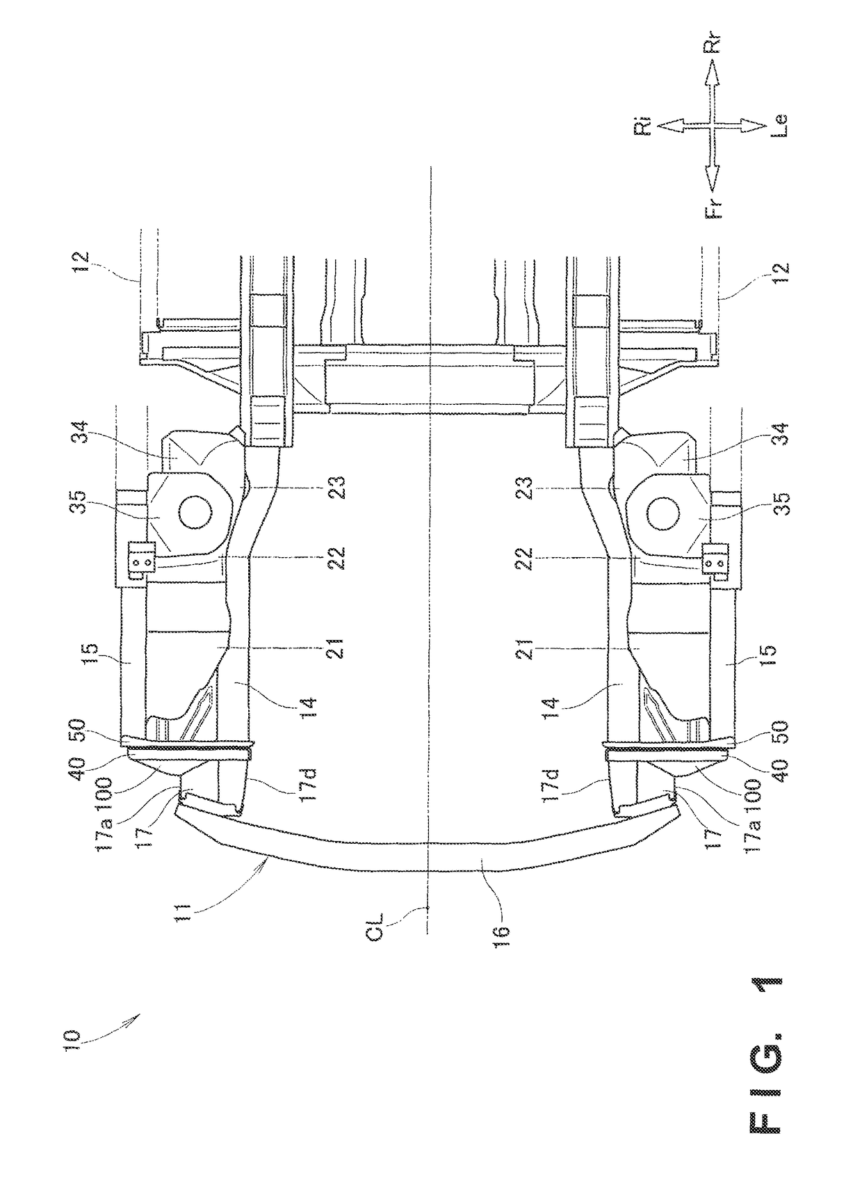
[0051]As shown in FIG. 1, a vehicle 10 such as a passenger car includes a frameless vehicle body 11. The vehicle body 11 is substantially formed to be bilaterally symmetric with respect to a vehicle width center line CL passing through the center of the vehicle 10 in the vehicle width direction and extending in the front-and-rear direction of the vehicle.

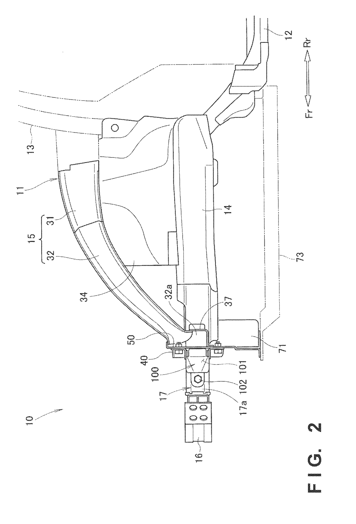
[0052]As shown in FIGS. 1 and 2, the front part of the vehicle body 11 includes left and right side sills 12, left and right front pillars 13 (only the left front pillar 13 is shown), left and right front s...


PUM


Abstract

There is provided a vehicle body front structure in which left and right frame side mounting members for connecting the rear ends of left and right bumper beam extensions are provided at the front ends. The left and right front side frames are formed from left and right side inner panels and left and right side outer panels. The left and right side outer panels are formed from left and right rear outer panels and left and right front outer panels. The left and right front outer panels are formed from left and right side plates, left and right upper plates, and left and right lower plates. At least one of the set of the left and right upper plates and the set of the left and right lower plates is formed by members different from the left and right side plates.

Description

BACKGROUND OF THE INVENTION[0001]Field of the Invention[0002]The present invention relates to a vehicle body front structure.[0003]Description of the Related Art[0004]In a vehicle such as a passenger car, a front bumper beam extending in the vehicle width direction is located at the front end of a vehicle body. Left and right bumper beam extensions extending to the rear side are provided at two ends of the front bumper beam in the longitudinal direction. The rear ends of the left and right bumper beam extensions are detachably connected to the front ends of left and right front side frames.[0005]In recent years, a technique of absorbing collision energy when a narrow offset collision occurs in the front part of a vehicle body has been developed. This technique is known from, for example, Japanese Patent No. 5537583.[0006]In a known vehicle body front structure disclosed in Japanese Patent No. 5537583, left and right gussets project outward in the vehicle width direction from the fro...

Claims


Application Information

Patent Timeline
Patent Type & Authority Patents(United States)
IPC IPC(8): B60N99/00B62D21/15B62D25/08B60R19/34
CPCB62D21/152B60R19/34B62D25/082B62D25/08B60Y2304/05B60Y2304/03
Inventor NAKAMOTO, NAOKIKOBAYASHI, SHINYAMATSUSHIMA, YUKI
Owner HONDA MOTOR CO LTD
Why Eureka
Try Eureka