Disk drive base with decreased thickness portion angle being less than increased thickness portion angle

a technology of a disk drive and a base, which is applied in the direction of instruments, carrier cases, data recording, etc., can solve the problems of the wall portion, affecting the stability of the mold, so as to improve the stability and stability of the mold and the cavity. , to achieve the effect of reducing the thickness, facilitating the separation of the cast base, and facilitating the spread of metal

Active Publication Date: 2018-06-05
NIDEC CORP
View PDF3 Cites 4 Cited by
  • Summary
  • Abstract
  • Description
  • Claims
  • Application Information

AI Technical Summary

Benefits of technology

[0006]The present invention has been conceived to provide a technique for facilitating separation of a cast base from a mold, and making it easier for a molten metal to spread throughout a portion of a cavity in the mold which corresponds to a decreased thickness portion when the base is cast.
[0008]According to the above preferred embodiment of the present invention, the wall portion includes an inner surface arranged to slant so as to extend radially outward away from the central axis while extending axially away from the bottom plate portion. This makes it easier to separate the cast base from a mold. In addition, the second slanting surface is arranged to protrude radially inward relative to the first slanting surface. This makes it easier for a metal to spread throughout a portion of a cavity in the mold which corresponds to the decreased thickness portion when the base is cast.

Problems solved by technology

Here, if a side surface of the wall portion extends completely in parallel with a direction in which the hardened base is separated from the mold, frictional resistance between the mold and the wall portion will be so great as to make the mold release difficult.
This will make it difficult for the molten metal to spread throughout a portion of a cavity in the mold which corresponds to the decreased thickness portion when the base is cast.
The above-described problem is particularly significant with a base used in a small-sized disk drive apparatus.

Method used


Image

  • Disk drive base with decreased thickness portion angle being less than increased thickness portion angle
  • Disk drive base with decreased thickness portion angle being less than increased thickness portion angle
  • Disk drive base with decreased thickness portion angle being less than increased thickness portion angle

Examples


Embodiment Construction

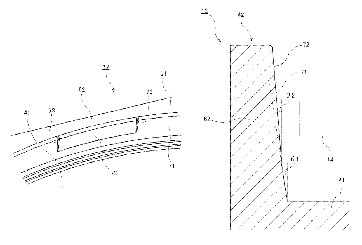
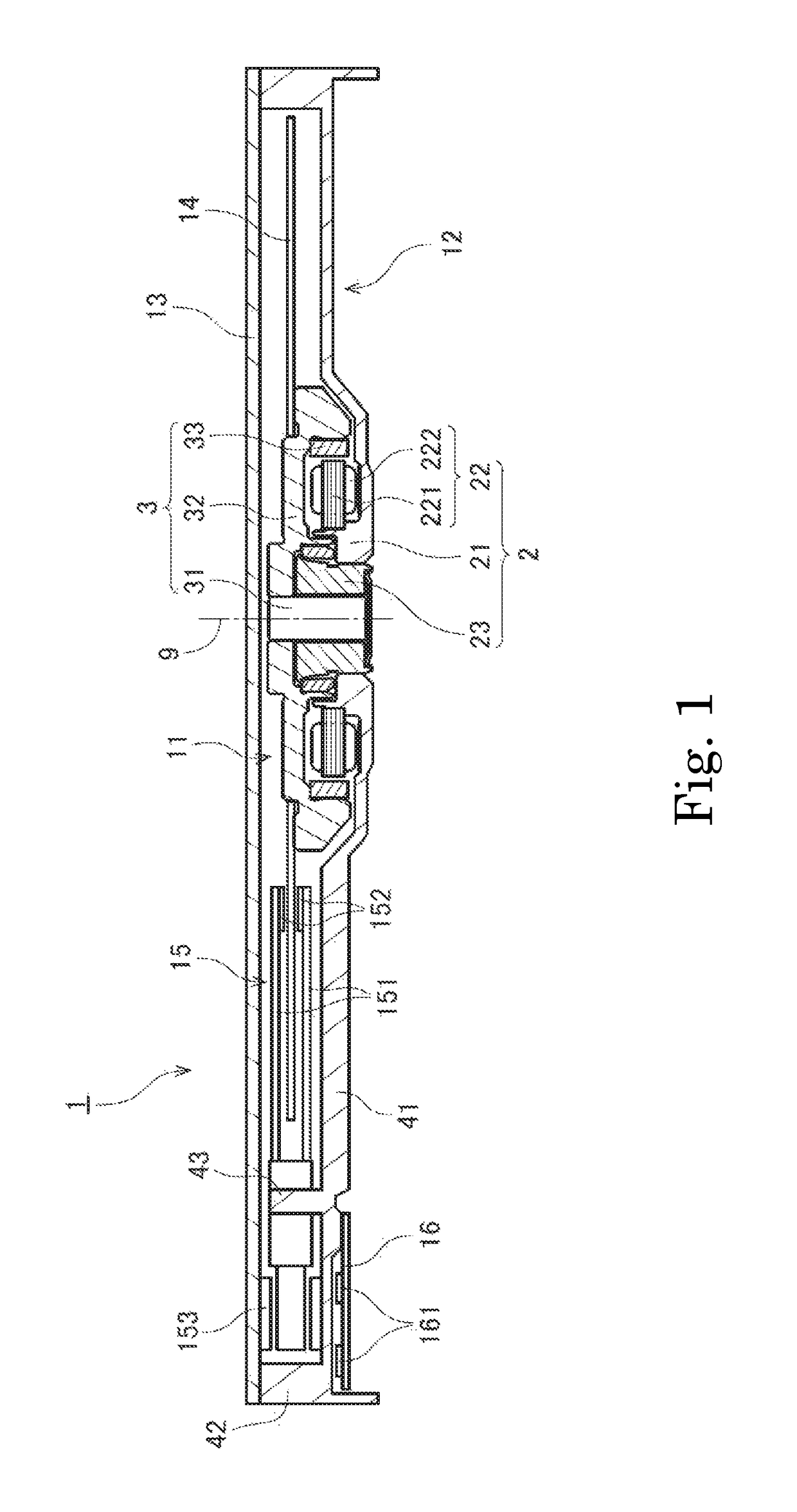
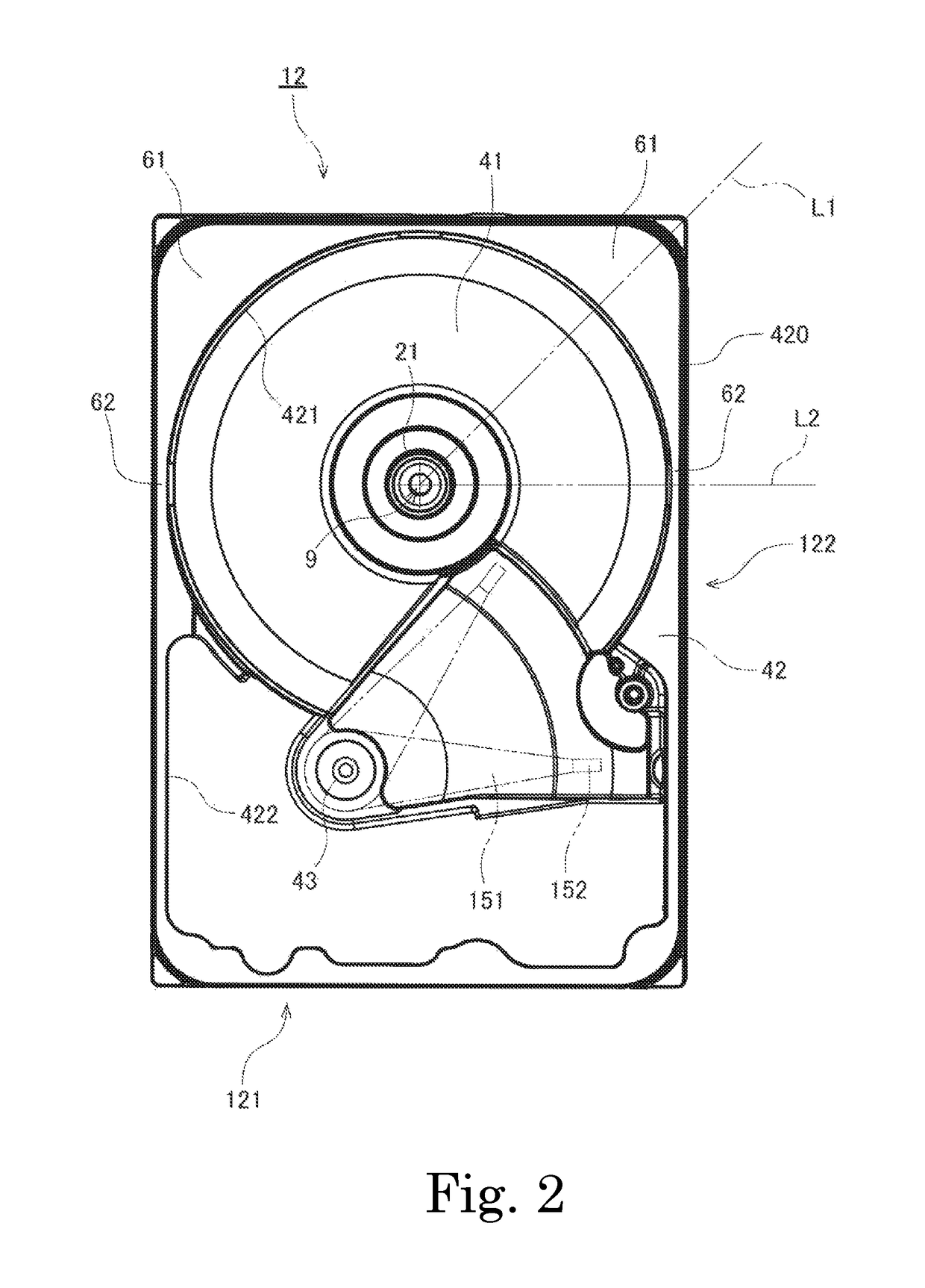
[0016]Hereinafter, preferred embodiments of the present invention will be described with reference to the accompanying drawings. It is assumed herein that a direction parallel to a central axis of a motor arranged to rotate a disk is referred to by the term “axial direction”, “axial”, or “axially”, that directions perpendicular to the central axis are each referred to by the term “radial direction”, “radial”, or “radially”, and that a direction along a circular arc centered on the central axis is referred to by the term “circumferential direction”, “circumferential”, or “circumferentially”. It is also assumed herein that an axial direction is a vertical direction, and that a side on which a cover is arranged with respect to a base is an upper side, and the shape of each member or portion and relative positions of different members or portions will be described based on the above assumptions. It should be noted, however, that the above definitions of the vertical direction and the up...


PUM

PropertyMeasurementUnit
inclination angleaaaaaaaaaa
inclination anglesaaaaaaaaaa
inclination angle θ2aaaaaaaaaa

Abstract

A base of a disk drive apparatus includes a bottom plate portion and a wall portion. The wall portion includes an increased thickness portion and a decreased thickness portion. An inner surface of the increased thickness portion includes a first slanting surface arranged to extend radially outward away from a central axis while extending axially away from the bottom plate portion. An inner surface of the decreased thickness portion includes a second slanting surface arranged to extend radially outward away from the central axis while extending axially away from the bottom plate portion, and protrude radially inward relative to the first slanting surface. An inclination angle of the second slanting surface with respect to an axial direction is arranged to be smaller than an inclination angle of the first slanting surface with respect to the axial direction.

Description

CROSS REFERENCE TO RELATED APPLICATIONS[0001]This application claims the benefit of priority to Japanese Patent Application No. 2017-125404 filed on Jun. 27, 2017. The entire contents of this application are hereby incorporated herein by reference.BACKGROUND OF THE INVENTION1. Field of the Invention[0002]The present invention relates to a base and a disk drive apparatus.2. Description of the Related Art[0003]A disk drive apparatus, such as, for example, a hard disk drive, has been known. The disk drive apparatus typically includes a spindle motor arranged to rotate a disk, a head arranged to perform reading and writing of information from or to the disk, and a base arranged to support the spindle motor and the head. A known base for use in a disk drive apparatus is described in, for example, JP-A 2009-245570. In a technique described in JP-A 2009-245570, a casting that is to become the base is defined by a die casting process, and thereafter, a disk opposed surface of a shroud is su...

Claims


Application Information

Patent Timeline
Patent Type & Authority Patents(United States)
IPC IPC(8): G11B33/02G11B25/04
CPCG11B33/022G11B25/04G11B25/043
Inventor ITO, MICHIHIROINO, YASUTAKAHARAGUCHI, MASAYA
Owner NIDEC CORP
Why Eureka
Try Eureka