Sound generator for mounting on a vehicle to manipulate vehicle noise

a sound generator and vehicle technology, applied in the direction of electrical transducers, instruments, electrical equipment, etc., can solve the problems of reducing the overall efficiency of the vehicle, not being able to achieve such a distinctive noise emission in a natural way, and being difficult to manufacture cost-effectively. , to achieve the effect of robust mounting and operation, and cost-effective manufactur

Active Publication Date: 2018-06-12
PUREM GMBH
View PDF43 Cites 3 Cited by
  • Summary
  • Abstract
  • Description
  • Claims
  • Application Information

AI Technical Summary

Benefits of technology

[0017]It is therefore an object of the present invention to provide a sound generator for a system for manipulating noises, and in particular exhaust noise, from vehicles driven by an internal combustion engine which reliability is improved, particularly with respect to an immersion of the sound generator into water. The sound generator is further supposed to be manufactured cost-efficiently and to be robust in mounting and operation.
[0019]Since the pressure compensation valve extends through the plane along which the loudspeaker is disposed, a pressure difference actually present between the two sides of the loudspeaker is relieved. The pressure compensation valve thus enables a particularly precise pressure compensation. Furthermore, any pumping out of the volume enclosed by the loudspeaker and the casing by the loudspeaker is avoided when the pressure outside of the volume enclosed by the loudspeaker and the casing but in front of the loudspeaker rises.
[0025]According to an embodiment, the at least one pressure compensation valve is disposed inside the casing with the valve body being dimensioned such that the valve body is disposed opposite to the plane in which the loudspeaker is located and at a maximum distance to the plane in which the loudspeaker is located. Since the loudspeaker is usually oriented downwards when the sound generator is mounted on a vehicle, the positioning of the valve body enables pressure compensation even when the sound generator is immersed completely in water. The feature “at a maximum distance” thereby indicates a positioning, where the valve body is as far away as possible from the plane in which the loudspeaker is located, but which still guarantees an adequate operation of the valve head. According to an embodiment, the feature “at a maximum distance” should be complied with when the distance between the valve body and a plane in which the loudspeaker is located (the loudspeaker extends along a loudspeaker plane) corresponds to at least ⅔ of a distance between an inner surface of the casing and the plane, with the distance being measured at a right angle to this plane.
[0033]The membrane may for instance be funnel-shaped, or spherically-dome-shaped, or have a non-developable NAWI-shape, as is usual for voice coil loudspeakers. The membrane may further be coupled to the loudspeaker basket by an airtight surround. Non-developable, bell-mouthed, or spherically-dome-shaped membranes are particularly rigid and enabling the membrane to move uniformly over its entire surface. Alternatively, also a conical membrane will do.

Problems solved by technology

Part of the noise propagates through the combustion engine in the form of structure-borne noise and is then emitted from the combustion engine's outside in the form of airborne noise.
These noises are often regarded as being harmful.
With state of the art small-displacement engines, it is no longer possible to achieve such a distinctive noise emission in a natural way.
The drawback of both modes of operation is that they require a comparatively large volume, and build up a relatively high resistance to the combusted air fuel mix, thereby reducing the overall efficiency of the vehicle and increasing its fuel consumption.
Irrespective of the sound generator being mounted in fluid communication with the exhaust system or separate from the exhaust system at a vehicle's underbody, placing the sound generator on the underbody of a vehicle causes several problems: firstly, the space available is usually very limited requiring a very compact design of the muffler, secondly, the sound generator has to be protected from environmental influences, and in particular from water and contamination.
A drawback of the above configuration is that the sound generator's pressure compensation valve frequently functions unreliably.
One reason being that the pressure compensation valve is easily damaged by impacts from the outside; the other that dust and water may easily clog the pressure compensation valve making any pressure compensation impossible.
Since pressure compensation valves are often designed for air to pass through but not for water to pass through, pressure compensation is often not possible, particularly when the pressure compensation valve of the sound generator is located below the surface of a water body.
This increases cost and may, due to the increased rigidity of the membrane involved therewith, and reduces the acoustic performance of the loudspeaker at low frequencies.
This, however, increases the effort for mounting the sound generator considerably.
A further problem with the configuration described above is that, when the exhaust system is submerged into water, an increased pressure is applied from outside to the membrane.
The above problems are also present, when the sound generator is not in fluid communication with the exhaust system different to the sound generator shown in FIGS. 1A and 1B.
For a sound generator that is not in fluid communication with the exhaust system there is also an increased risk of a membrane offset due to an increased outside pressure.

Method used


Image

  • Sound generator for mounting on a vehicle to manipulate vehicle noise
  • Sound generator for mounting on a vehicle to manipulate vehicle noise
  • Sound generator for mounting on a vehicle to manipulate vehicle noise

Examples


first embodiment

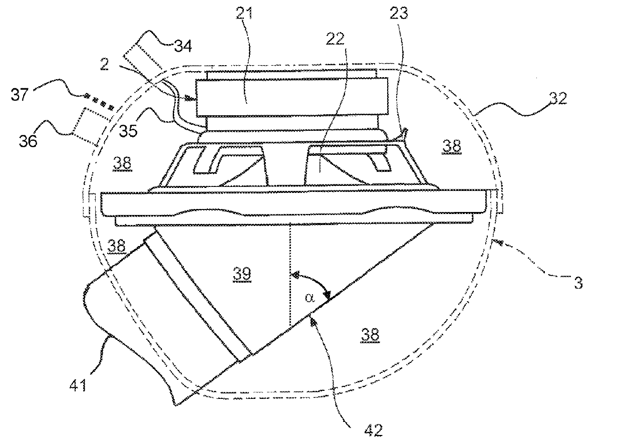
[0058]Referring to the drawings, a sound generator according to the invention is described referencing FIG. 2A. FIG. 2A thereby shows a cross-section through the sound generator 100 in a schematic view.

[0059]The sound generator 100 shown in FIG. 2A comprises a casing 110 formed from a lower shell 113 and an upper shell 112 coupled to the lower shell 113 in an airtight manner. Both, the lower shell 113 and the upper shell 112 are made from a stainless steel panel.

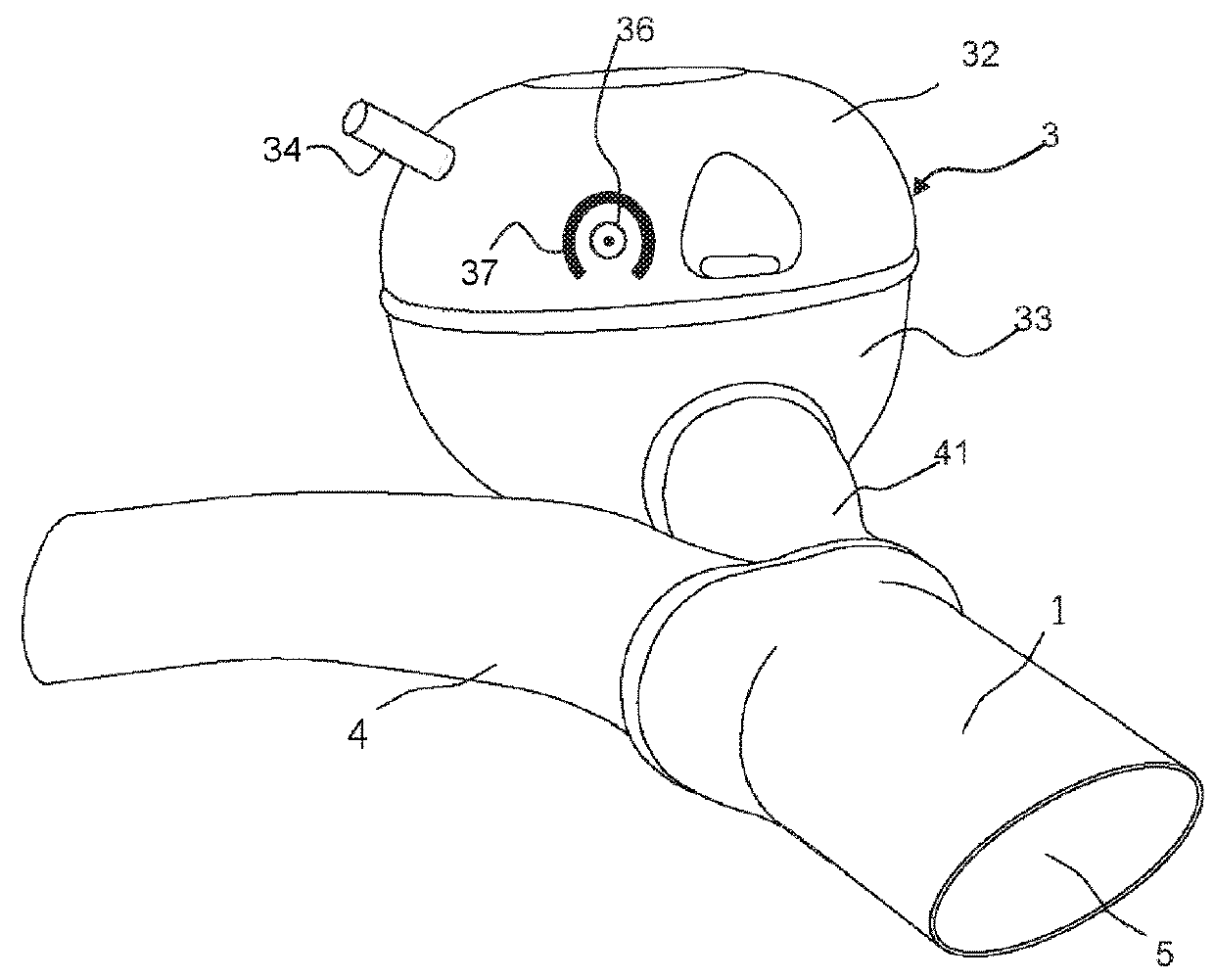
[0060]The lower shell 113 of the casing 110 includes a casing aperture 111 and receives a bell mouth 140 also made from a stainless steel panel. In the region of the casing aperture 111 an outside of the bell mouth 140 is coupled to the lower shell 113 of the casing 110 in an airtight manner. An opening of the bell mouth 140 is aligned with the casing aperture 111 of the sound generator 100. The bell mouth 140 of the embodiment illustrated is configured for being coupled to an exhaust system as shown in FIG. 1A for a prior a...

fourth embodiment

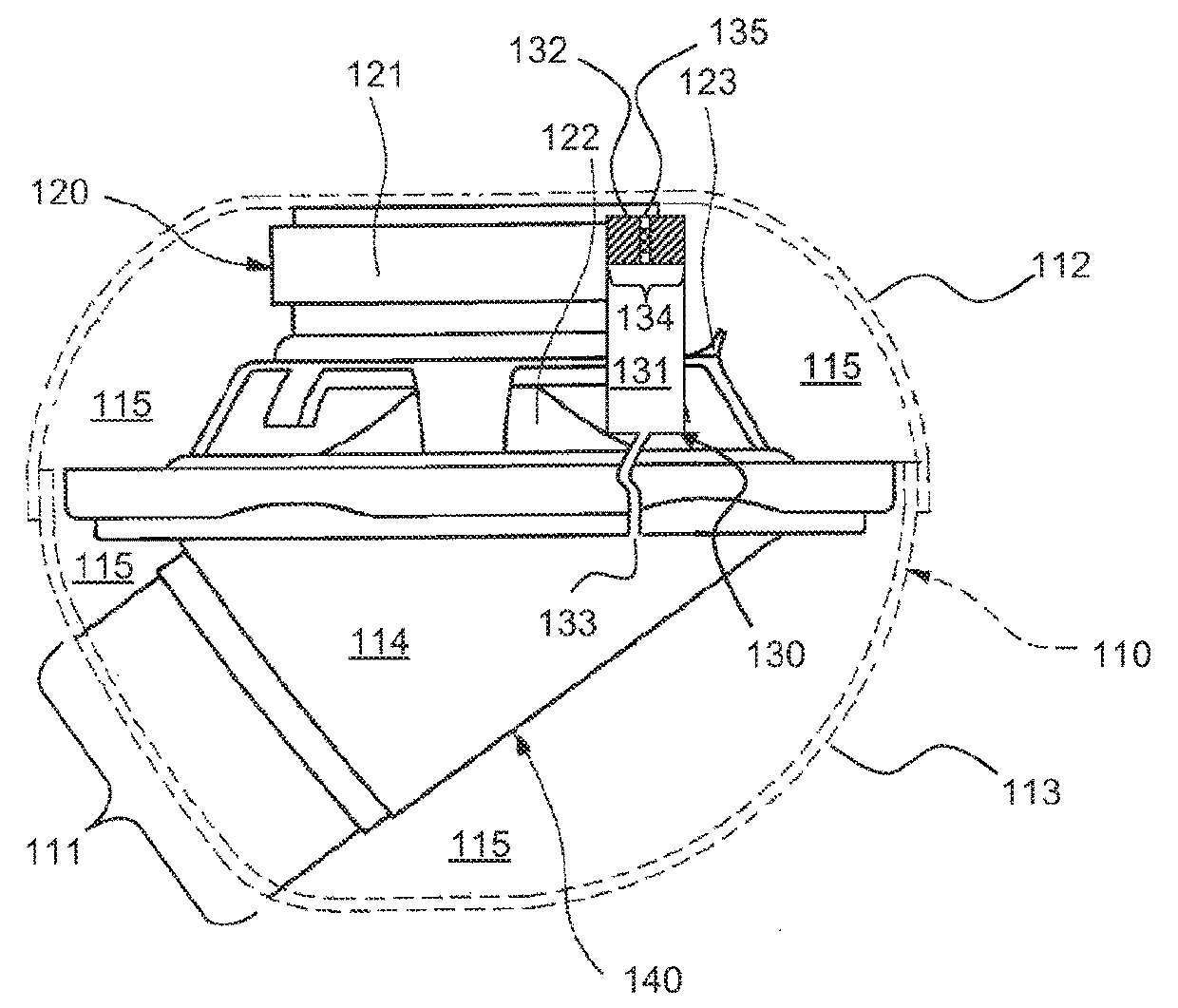
[0073]Further, no bell mouth is present inside the casing 110 of the sound generator 100 and the casing 110 is also not made in two parts by an upper shell and a lower shell. The casing is rather made cup-shaped from polyvinyl chloride and is sealed by the loudspeaker basket 123 of the voice coil loudspeaker 120 supported by the casing 110. This results in the voice coil loudspeaker 120 separating the rear volume 115 enclosed by the loudspeaker 120 and the casing 110 from the air 114′ at the other side of the voice coil loudspeaker 120. Hence, the rear volume 115 communicates also in this case only through the pressure compensation valve 130 with air 114′ on the other side of the voice coil loudspeaker 120.

[0074]FIG. 3A illustrates a first operating condition, where only air 114′ surrounds the sound generator 100. A pressure compensation between the rear volume 115 and the air 114′ on the other side of the voice coil loudspeaker 120 through the pressure compensation valve 130 is po...


PUM


Abstract

A sound generator (100) mounts on a vehicle to manipulate vehicle noise originating from a vehicle operated by an internal combustion engine. The sound generator (100) includes a casing (110), a loudspeaker (120), and at least one pressure compensation valve (130). The loudspeaker (120) and the casing (110) together thereby enclose a volume (115). Further, the pressure compensation valve (130) couples the volume (115) enclosed by the loudspeaker (120) and the casing to an outside of the casing (110). The pressure compensation valve (130) thereby extends through a plane in which the loudspeaker (120) is located. A system (200) for manipulating sound waves propagating through exhaust systems of vehicles driven by an internal combustion engine uses the above sound generator (100).

Description

CROSS REFERENCE TO RELATED APPLICATIONS[0001]This application claims the benefit of priority under 35 U.S.C. § 119 of German Application 10 2015 119 191.1 filed Nov. 6, 2015, the entire contents of which are incorporated herein by reference.FIELD OF THE INVENTION[0002]The invention relates to a sound generator for mounting on a vehicle to manipulate vehicle noise. The vehicle may be a vehicle driven by an internal combustion engine or electrically, and in particular a motor vehicle. The sound generator may, in particular, be part of a system for manipulating sound waves traveling through exhaust systems of vehicles driven by an internal combustion engine.BACKGROUND OF THE INVENTION[0003]Irrespective of the internal combustion engine type (for example piston engine, rotary engine or free-piston engine), noises are generated due to the cycle of strokes (notably the induction and compression of an air fuel mix, power, and exhaust of the combusted air fuel mix). Part of the noise propag...

Claims


Application Information

Patent Timeline
Patent Type & Authority Patents(United States)
IPC IPC(8): G10K11/16F01N1/16G10K11/178F01N13/18F01N1/06H04B1/00H04R9/06
CPCF01N1/065F01N1/166F01N13/1866G10K11/178G10K2210/128H04R9/06H04R2499/13G10K2210/127G10K11/17857G10K11/17883
Inventor NICOLAI, MANFREDSCHMIDT, THOMASKRUGER, JAN
Owner PUREM GMBH
Why Eureka
Try Eureka