Timber-working head and method of operation

a technology of timberworking head and pivoting arm, which is applied in the field of controlling the pivoting arms of the timberworking head, can solve the problems of less than optimal feed performance, damage to the stem, and ill-formed stems of the harvester head, so as to reduce the likelihood of the stem grating against the side, and maximize the value of the log cut

Active Publication Date: 2018-06-19
WARATAH NZ
View PDF10 Cites 0 Cited by
  • Summary
  • Abstract
  • Description
  • Claims
  • Application Information

AI Technical Summary

Benefits of technology

[0024]While it may be useful to allow independent movement of the arms to allow for irregularities in the profile of the timber, it may also be desirable to maintain the lateral position of the stem within certain limits relative to the feed axis of the timber-working head. In particular, it may be desirable for the stem to be held roughly centre in order to align it with delimbing blades, and maintain maximum traction by the feed wheels. Further, it may be desirable for the stem to be held such the saw may perform a cut at a substantially 90 degree angle. As the length measurement is taken from the shortest side of a cut log, achieving a square cut may assist in maximizing the value of the log cut.
[0025]It should be appreciated that the predetermined distance may vary between different configurations of timber-working heads, particularly with regard to the dimensions of the heads themselves and the diameter of timber expected to be processed. Movement of the stem may generally limited by the harvester body itself. Control of the travel within this may account for maintaining a minimum gap between the harvester and the stem to reduce the likelihood of the stem grating against the side and potentially causing damage to the stem and / or harvester. Variation in the stem due to sweep or other contour irregularities may also be taken into consideration.

Problems solved by technology

However, the stems processed by the harvester head may be ill-formed, for example having sweep (i.e. variation in the axial linearity of the stem) or other contour irregularities (e.g. bulges, depressions, lack of circularity).
This can cause hydraulic oil to bypass, leading to one wheel slipping and spinning—causing less than optimal feed performance and potentially damage to the stem by the slipping wheel ripping into the surface.
There can also be further ramifications in terms of damage to the motors themselves as the result of this slipping and motor cavitation.
The mechanical link also adds weight and complexity to the harvester—particularly in the steel support frame and pins required for pivotal connection—which in turns adds to the cost of manufacture.
These also create potential points of mechanical failure, particularly where ill-formed stems lead to an imbalance of forces being applied to the two arms—essentially attempting to rip them apart.
As the operation of the feed arms is a crucial component of many, if not all, of the functions of a harvester head, time required to repair the link may reduce the productivity of the forestry work machine.

Method used


Image

  • Timber-working head and method of operation
  • Timber-working head and method of operation
  • Timber-working head and method of operation

Examples


Embodiment Construction

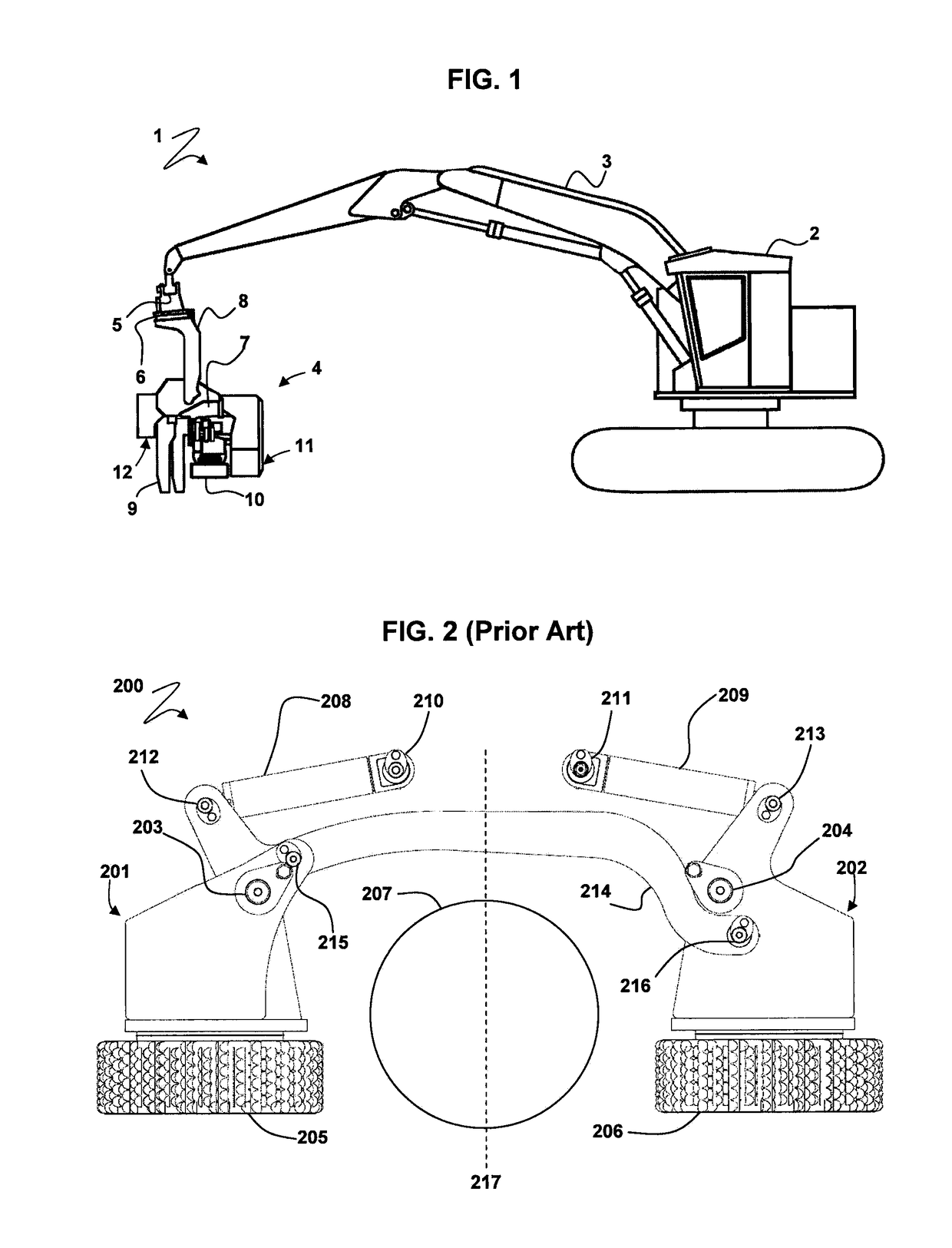
[0038]FIG. 1 illustrates an exemplary forestry work machine (generally indicated by arrow 1) comprising a carrier 2 supporting an articulated boom 3. An exemplary timber working implement in the form of a harvester head 4 is connected to an end of the boom 3, using a dog-bone joint 5 connected to a rotator 6, which is in turn connected to a frame 7 of the head 4 by hanger 8. In operation, the head 4 may swivel relative to the end of the boom 3 about the rotator 6, and pivotally move about its connection to the hanger 8 between a generally upright, harvesting position for felling a tree (not illustrated) and a generally prone, processing position (as illustrated) for processing the felled tree (e.g., delimbing, debarking, cutting to length).

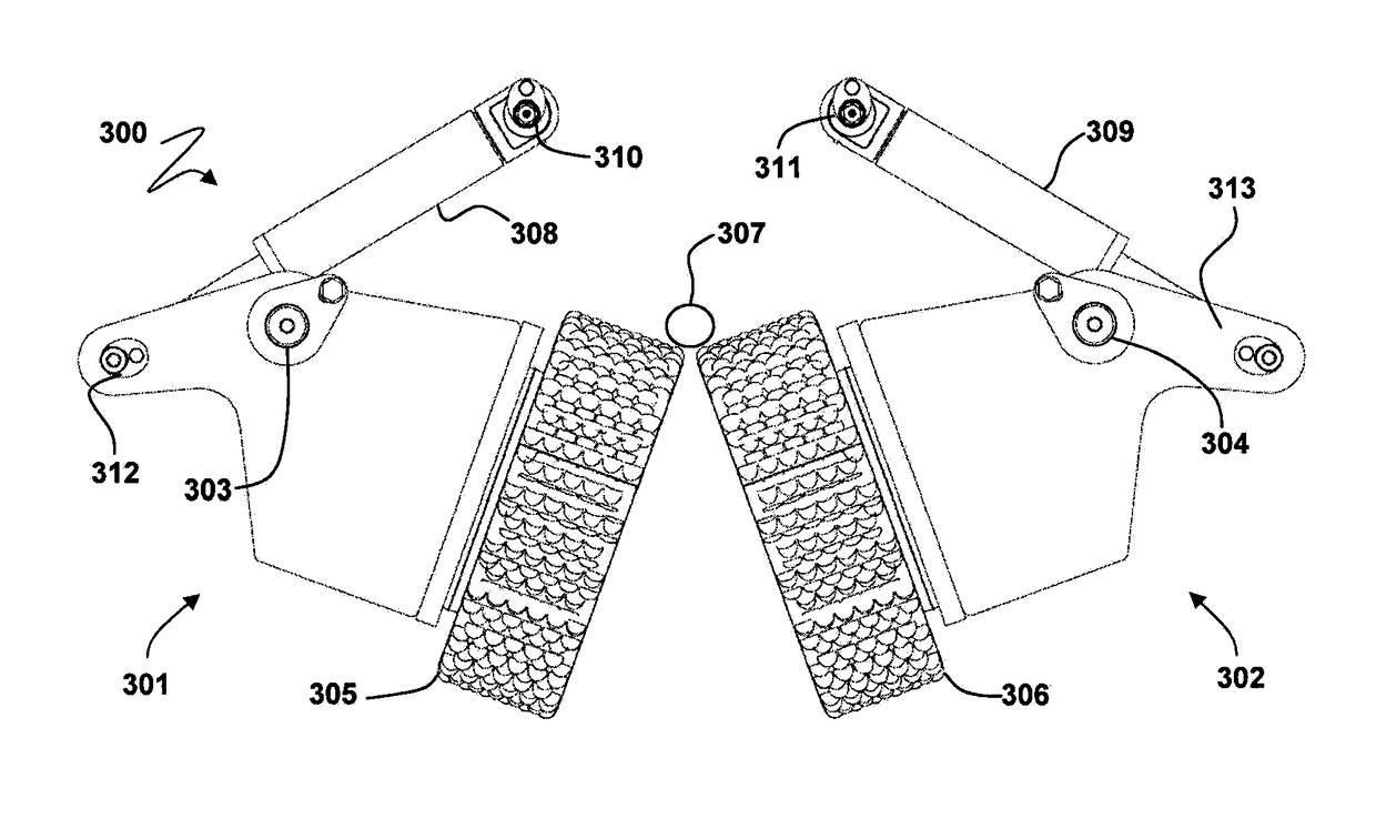
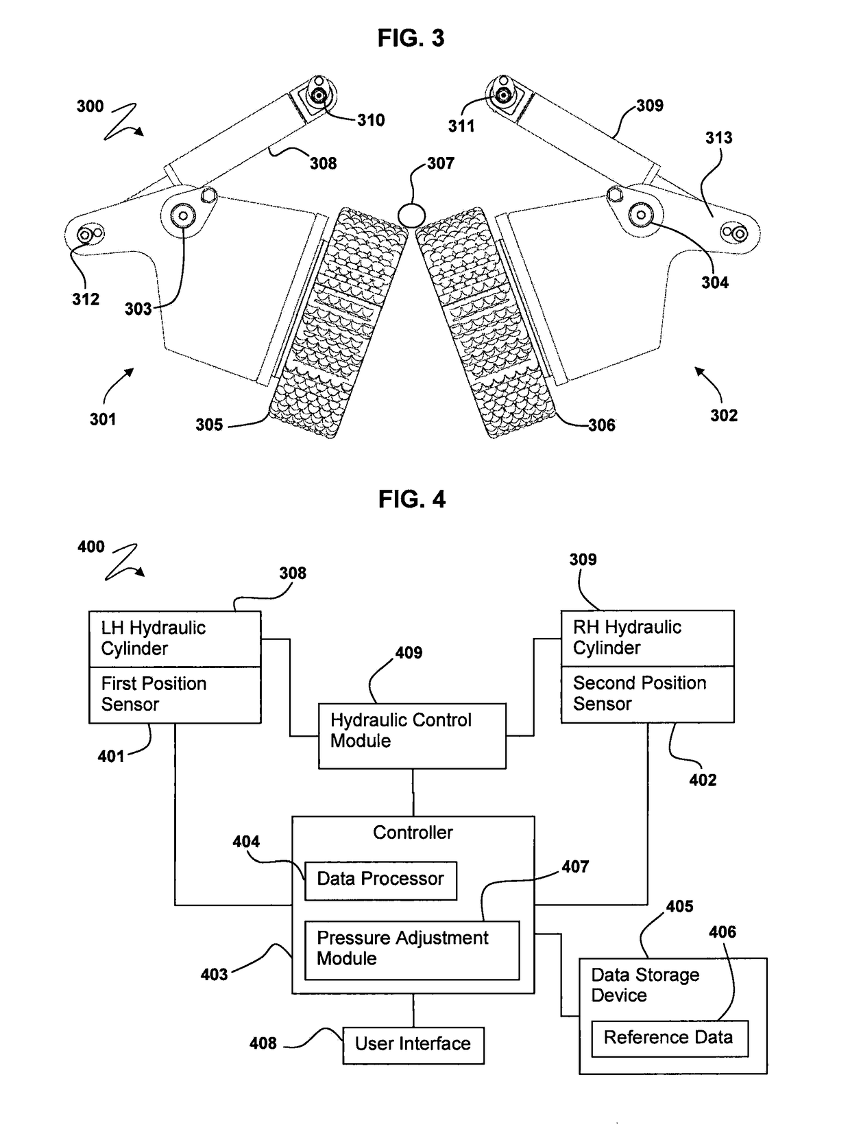
[0039]The harvester head 4 comprises a pair of grapple or delimbing arms 9 pivotally connected to the frame 7 and configured to grasp the stem of the tree. The head 4 also comprises a pair of feed arms 10 pivotally connected to the frame 7 and com...


PUM


Abstract

A timber-working head and method of operation are provided. The head has a frame to which first and second arms are pivotally connected. Respective linear drive actuators pivot the respective arms relative to the frame to open and close them. At least one processor controls application of pressure by the linear drive actuators such that the arms grasp timber to be processed by the head. The position of the linear actuators is used to determine whether the timber is offset from a feed axis of the frame beyond a predetermined distance, and the application of pressure by one of the linear actuators to reduce the offset to be within the predetermined distance.

Description

CROSS-REFERENCE TO RELATED APPLICATION(S)[0001]This application claims priority under 35 U.S.C. § 119 to New Zealand Patent Application No. 607713, filed Feb. 28, 2013, the entire contents of which are incorporated herein by reference.STATEMENT OF FEDERALLY SPONSORED RESEARCH OR DEVELOPMENT[0002]Not applicable.FIELD OF THE DISCLOSURE[0003]The present disclosure relates to a timber-working head, and more particularly to a system and method for controlling pivoting arms of a timber-working head.BACKGROUND OF THE DISCLOSURE[0004]It is well-known to mount a timber-working head, for example in the form of a harvesting head, to a forestry work machine to perform a number of functions in connection with timber. Such heads may be used to grapple and fell a standing tree and process the felled tree by delimbing, possibly debarking (depending on the configuration of the head), and cutting the stem of the tree into logs of predetermined length.[0005]Processing the felled tree typically involve...

Claims


Application Information

Patent Timeline
Patent Type & Authority Patents(United States)
IPC IPC(8): A01G23/08A01G23/083
CPCA01G23/083
Inventor KAYE, BRETT JAMES
Owner WARATAH NZ
Why Eureka
Try Eureka