Sheet stapler

a stapler and sheet metal technology, applied in the field of sheet metal staplers, can solve the problems of cumbersome work, decreased operational efficiency, and inability to perform stapling operations, and achieve the effect of eliminating cumbersome prefeeding operations

Inactive Publication Date: 2000-10-24
CANON KK
View PDF20 Cites 264 Cited by
  • Summary
  • Abstract
  • Description
  • Claims
  • Application Information

AI Technical Summary

Benefits of technology

It is another object of the present invention to provide a stapler wherein a predetermined overload of the driver for the stapler is detected, and the driver drives in a reversed direction before the driver stops to retract the stapling station, by which the problems described above are eliminated.
A further object of the present invention is to provide a stapler wherein the cumbersome prefeeding operation is eliminated, or wherein a problem resulting when the set of sheets to be stapled is not actually stapled is corrected.

Problems solved by technology

However, the electric stapler disclosed in U.S. Pat. No. 4,573,625 is not provided with any detecting means for detecting staple jam, a blank shot resulting from failure of the staple feed or the like.
In this case, the stapler is stopped while gripping the sheets, and therefore, the operator has to manipulate the driver to release the gripped sheets, thus requiring cumbersome work.
Particularly, when the stapler is operated with a sorter or the like for continuously processing the sheets, the continuous processing operation is interrupted by the stopping of the stapler, and therefore, the operational efficiency is decreased.
In such a stapler, a leading edge of a strip of a series of staples does not reach the stapling means immediately after the staple cartridge is exchanged, and therefore, the stapling operation is not possible, if the stapler is operated as it is.
In addition, it is unknown to the operator how many blank shots are required, and therefore, the blank shots have to be executed with some sheets set in the stapling station, since otherwise the staple jam will occur.
Thus, the pre-feeding operation is very cumbersome.
Particularly, when the blank shot occurs in a stapler interrelated with an image forming apparatus such as a copying machine to sequentially staple sets of sheets discharged therefrom, the sheets can be scattered or can be jammed.

Method used


Image

  • Sheet stapler
  • Sheet stapler
  • Sheet stapler

Examples


Embodiment Construction

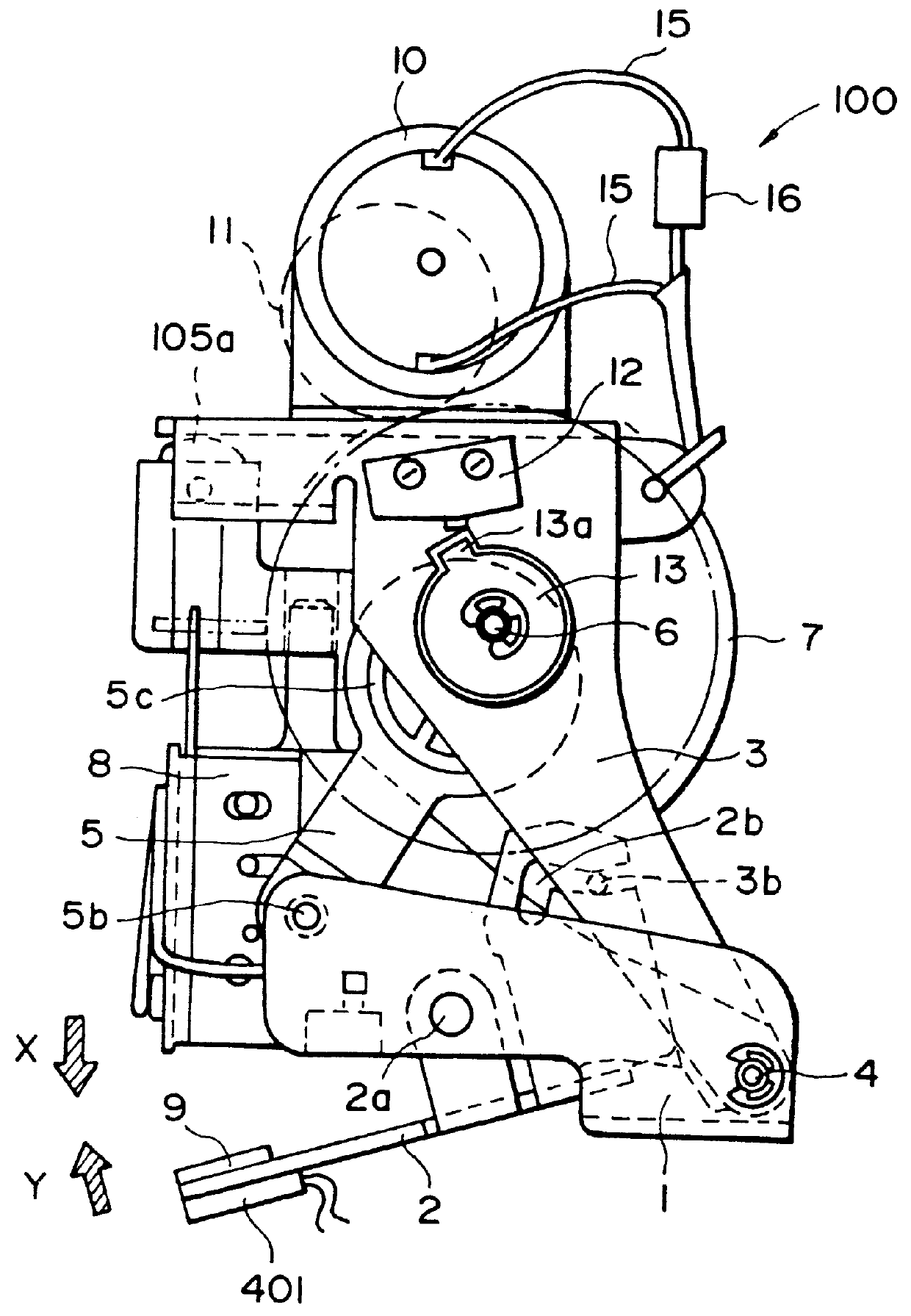
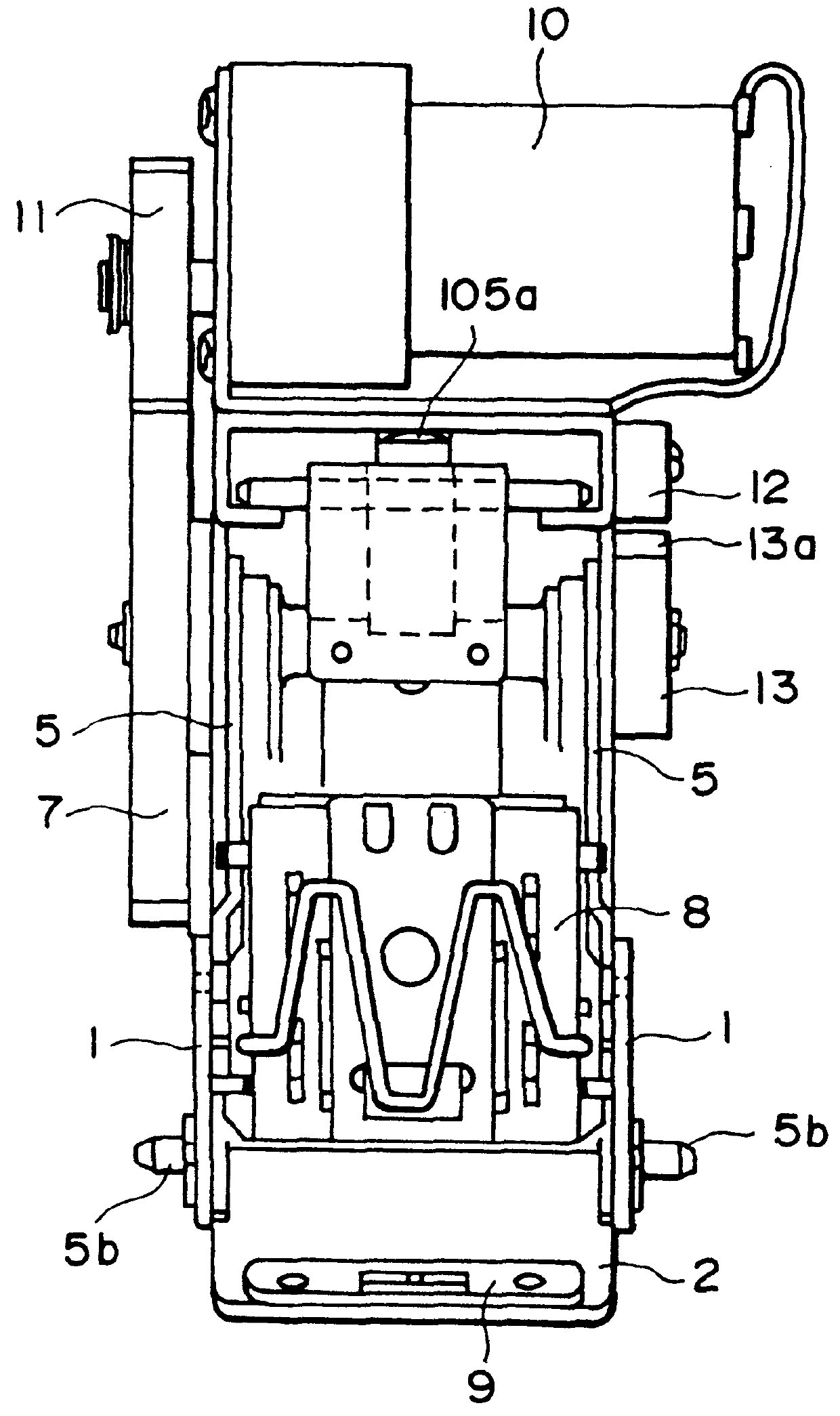
Referring first to FIGS. 2 and 3, there are shown front and side views of a stapler according to an embodiment of the present invention. As shown in FIG. 2, the stapler 100 includes a base 1 which is fixed, a lower jaw 2 rotatable about a pin 2a and an upper unit 3. At an end of the lower jaw 2, a channel-shaped cam 2b is formed and is engaged with a cramping pin 3b fixed to the upper unit 3. The upper unit 3 is swingably supported on a hinge pin 4 mounted to the base. A crank arm 5 is rotatably supported on a part of base 1 by a pin 5b adjacent an end of the crank arm 5. The other end thereof is engaged with a cam plate 5c fixedly and eccentrically mounted to a drive shaft 6. When a stapler gear 7 rotates through one full turn, the cam plate 5c rotates about the pin 6. At this time, since the base 1 is fixed, and since the distance between the pin 5b and the pin 6 is constant, the upper unit 3 rotates about the hinge pin 4 relative to the base 1. Also, a body 8 is pushed by a head ...


PUM

PropertyMeasurementUnit
period of timeaaaaaaaaaa
currentaaaaaaaaaa
stapling speedaaaaaaaaaa

Abstract

A sheet stapling apparatus including a stapling device for stapling a set of sheets, a load detecting device for detecting a level of a load of the stapling device during a stapling operation, and a signal generating device for generating a signal when the load detected by the load detecting device is outside a predetermined range.

Description

FIELD OF THE INVENTION AND RELATEDThe present invention relates to a sheet stapler for stapling sheets.An example of a conventional electric stapler is disclosed in U.S. Pat. No. 4,573,625, and comprises a staple cartridge containing a number of staples connected in the form of a belt or strip, a stapling section for stapling the sheets with the staples and a driver such as a motor for driving the stapling section, wherein the sheets brought into the stapling section are stapled using the motor.However, the electric stapler disclosed in U.S. Pat. No. 4,573,625 is not provided with any detecting means for detecting staple jam, a blank shot resulting from failure of the staple feed or the like.The driver in the form of a motor or the like of the electric stapler is occasionally imposed with a load beyond its capacity and is stopped sometimes, when, for example, to many sheets are attempted to be stapled at once, when a staple shoots an already stapled portion, or when thick or hard sh...

Claims


Application Information

Patent Timeline
Patent Type & Authority Patents(United States)
IPC IPC(8): B27F7/38B27F7/36B27F7/00B27F7/23
CPCB27F7/23B27F7/38B27F7/36
Inventor HIROI, MASAKAZUMURAKAMI, KOICHITAKAHASHI, YUJI
Owner CANON KK
Why Eureka
Try Eureka