System for identifying object locations

a technology for identifying objects and locations, applied in the field of object location systems, can solve the problems of inconvenient wear or attachment, continual drain on the power source, and bulky and cumbersome portable units

Inactive Publication Date: 2002-01-29
EXECUTONE INFORMATION SYST
View PDF29 Cites 186 Cited by
  • Summary
  • Abstract
  • Description
  • Claims
  • Application Information

AI Technical Summary

Benefits of technology

In still another embodiment of the present invention, the receivers are coupled to a PBX, which is coupled to the central computer and a plurality of telephones throughout the facility. The badge identification information is reported to the PBX and / or the central computer, facilitating the retrieval of location information of any identified personnel from any telephone connected to the PBX.

Problems solved by technology

One problem with the systems of this type is in the portable units.
The portable units became bulky and cumbersome and therefore inconvenient to be worn or attached.
A disadvantage of this type of location system is the large amount of energy required to periodically transmit information from a portable unit, causing a continual drain on the power source.
Further, unless the portable unit is efficiently used, frequent battery replacement and maintenance is required.

Method used


Image

  • System for identifying object locations
  • System for identifying object locations
  • System for identifying object locations

Examples


Embodiment Construction

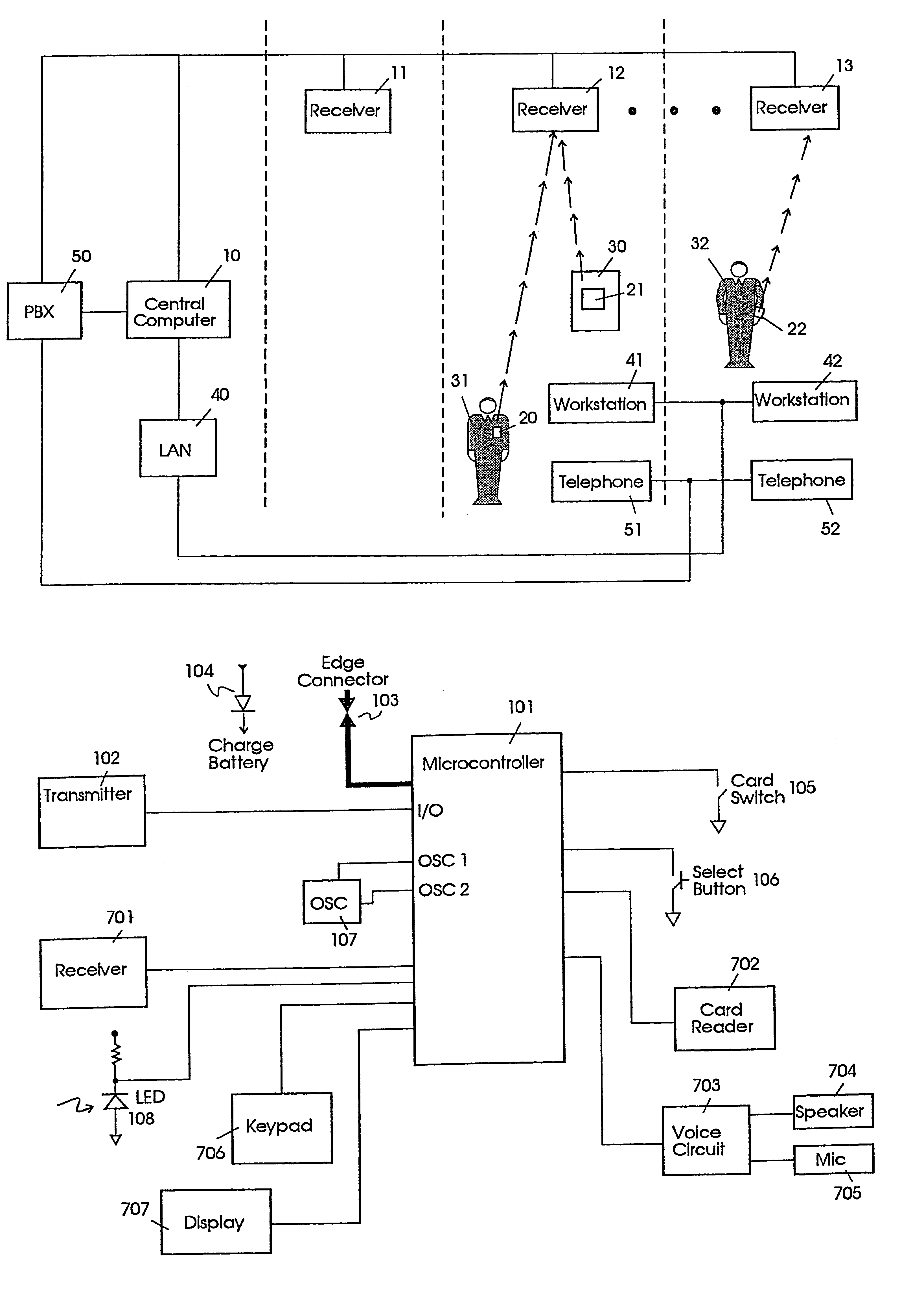
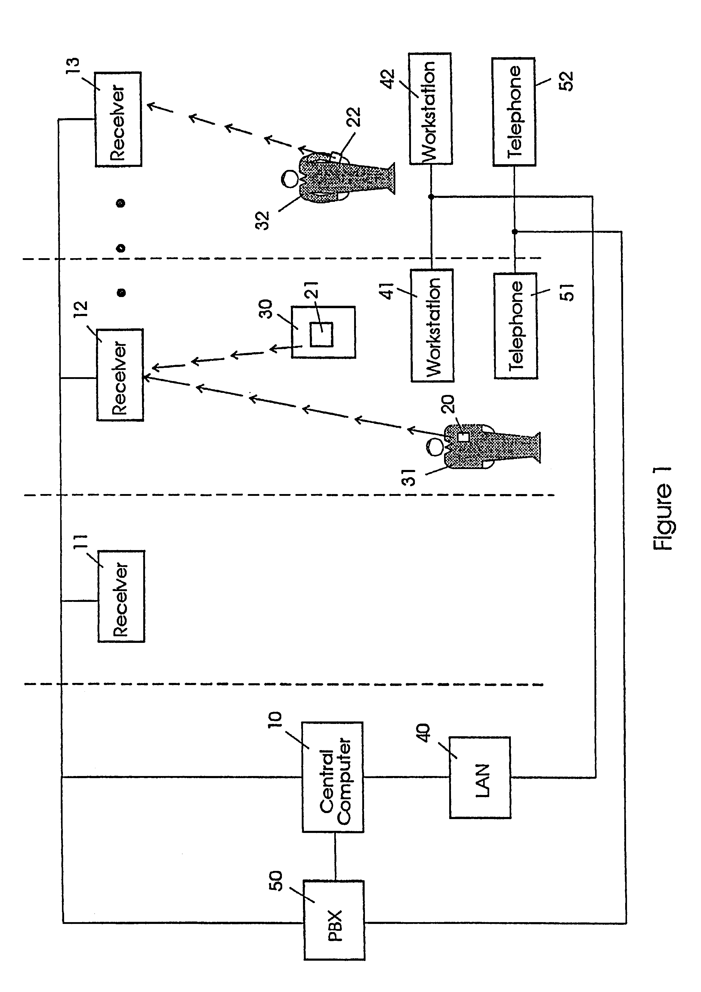
FIG. 1 illustrates the components of the location system according to the present invention.

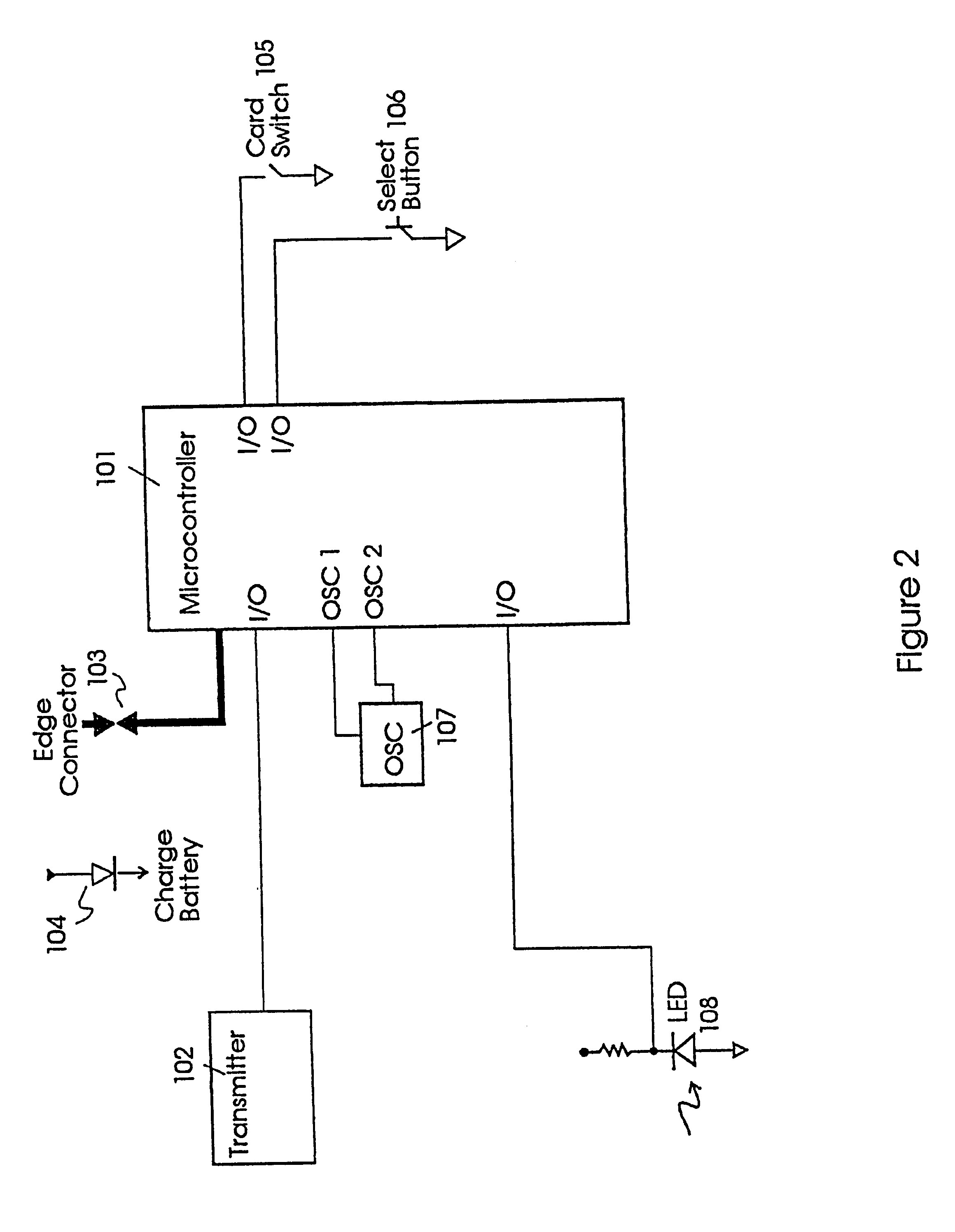
FIG. 2 is a block diagram of the components of the basic badge unit according to the present invention.

FIG. 3 is a flow diagram of the operation of the basic badge unit according to the present invention.

FIG. 4 is a block diagram of the components of the badge unit transmitter according to the present invention.

FIG. 5 is a block diagram of the components of the receiver unit according to the present invention.

FIG. 6A illustrates the bracelet embodiment according to the present invention;

FIG. 6B illustrates the top view of the housing for attachment to the bracelet;

FIG. 6C illustrates the top view of the housing when the housing is opened;

FIG. 6D illustrates the side view of the housing of the bracelet.

FIG. 7 illustrates a block diagram of an alternate embodiment of the badge unit according to the present invention.

FIG. 8A illustrates the side view of the housing of the badge unit according to...


PUM


Abstract

An objection location system for locating and communicating with personnel or objects within a facility. Remote badges are coupled to respective objects or personnel to be located. The badges include transmission means for transmitting identification information associated with their respective objects or personnel. Operational parameters are stored in the badges and are monitored for controlling the operation of the badges. The badge may be in the form of a wristband.

Description

TECHNICAL FIELD OF THE INVENTIONThis invention relates to an object location system, more particularly a system having a compact and intelligent badge or bracelet attached to an object for determining the location of the object.BACKGROUND OF THE INVENTIONLocation systems for locating objects or personnel within a facility are known. One type of personnel location system used in hospitals involves personnel within the facility reporting their locations by manually setting switches at designated areas. The switches are monitored at a central station and the locations of the personnel are determined by the locations of the activated switches. Other proposed personnel or object location techniques include systems which locate personnel or objects by seeking out where the object or personnel is closest to designated monitors. Such systems generally include a central controller connected in a plurality of transceivers distributed at designated locations throughout a facility. Portable uni...

Claims


Application Information

Patent Timeline
Patent Type & Authority Patents(United States)
IPC IPC(8): G07C9/00G08B3/10G08B3/00G08B5/22H04M3/42H04M11/00
CPCG06K7/10079G08B3/1083G08B5/222G07C9/28
Inventor CHACO, JOHNRAM, YARON
Owner EXECUTONE INFORMATION SYST
Why Eureka
Try Eureka