Clutch cover assembly

a technology of clutch disc and assembly, which is applied in the direction of friction clutches, mechanical actuated clutches, and clutch disc assemblies, can solve the problems of shortening the life of the clutch disc assembly and the clutch disc assembly, and the inability to maintain the initial pressing load of the diaphragm spring 154, so as to maintain the initial pressing load correctly and simple structure

Inactive Publication Date: 2002-06-18
EXEDY CORP
View PDF19 Cites 1 Cited by
  • Summary
  • Abstract
  • Description
  • Claims
  • Application Information

AI Technical Summary

Benefits of technology

It is an object of the present invention to maintain the initial pressing load of the pressing member by compensating for displacement due to wear on friction members.
When the friction members are worn, the movement regulation mechanism moves the support mechanism toward the friction members so that the initial pressing posture and the initial pressing load of the pressing members are maintained. It is possible to maintain the initial pressing load correctly since the pressing posture of the pressing member is maintained by moving the pressing member toward the friction members. It is precise and of simple structure.

Problems solved by technology

Excessive wear on the friction members shortens the lives of the clutch disc assembly and the clutch disc assembly.
Therefore, design requirements make it difficult to maintain the initial pressing load of the diaphragm spring 154.
As a result, it is impossible to maintain the posture of the initial pressing load of the diaphragm spring 154.

Method used


Image

  • Clutch cover assembly
  • Clutch cover assembly
  • Clutch cover assembly

Examples


first embodiment

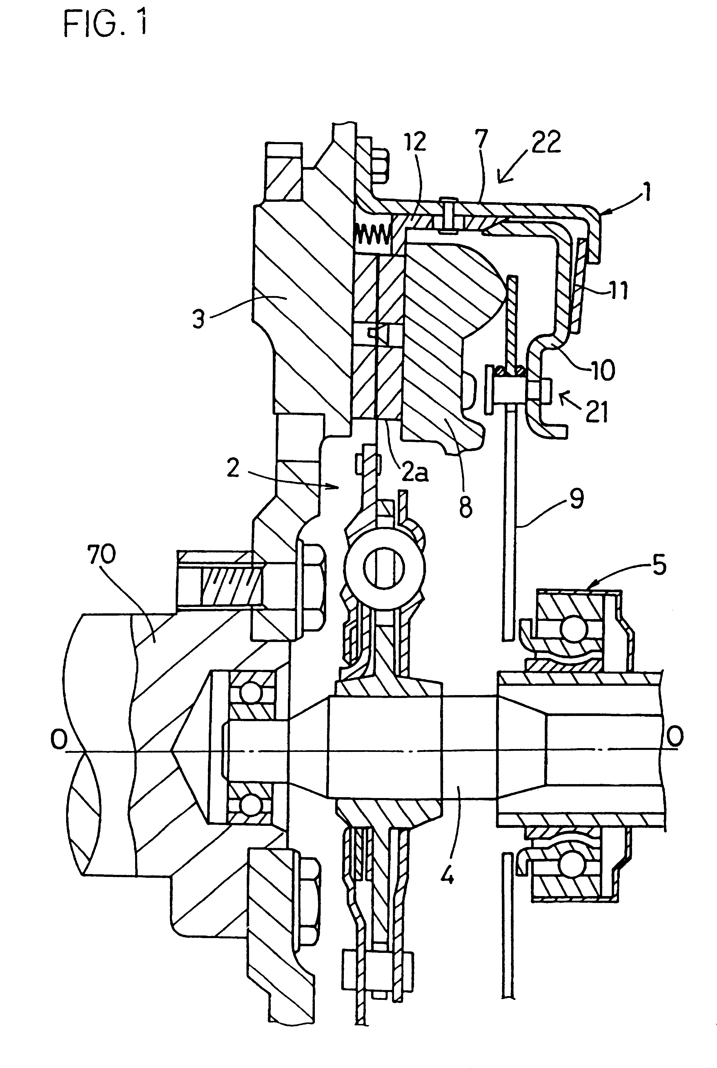
FIG. 1 shows a clutch to which the first embodiment of the present invention is applied. The clutch is principally composed of a clutch cover assembly 1 fixed to a flywheel 3, and a clutch disc assembly 2. The flywheel 3 is fixed to a crankshaft 70 of the engine. A main drive shaft 4, extending from the transmission side (right in FIG. 1), is spline-engaged with the center of the clutch disc assembly 2. A release bearing 5 of the release assembly is located around the main drive shaft 4 so as to move in the axial direction.

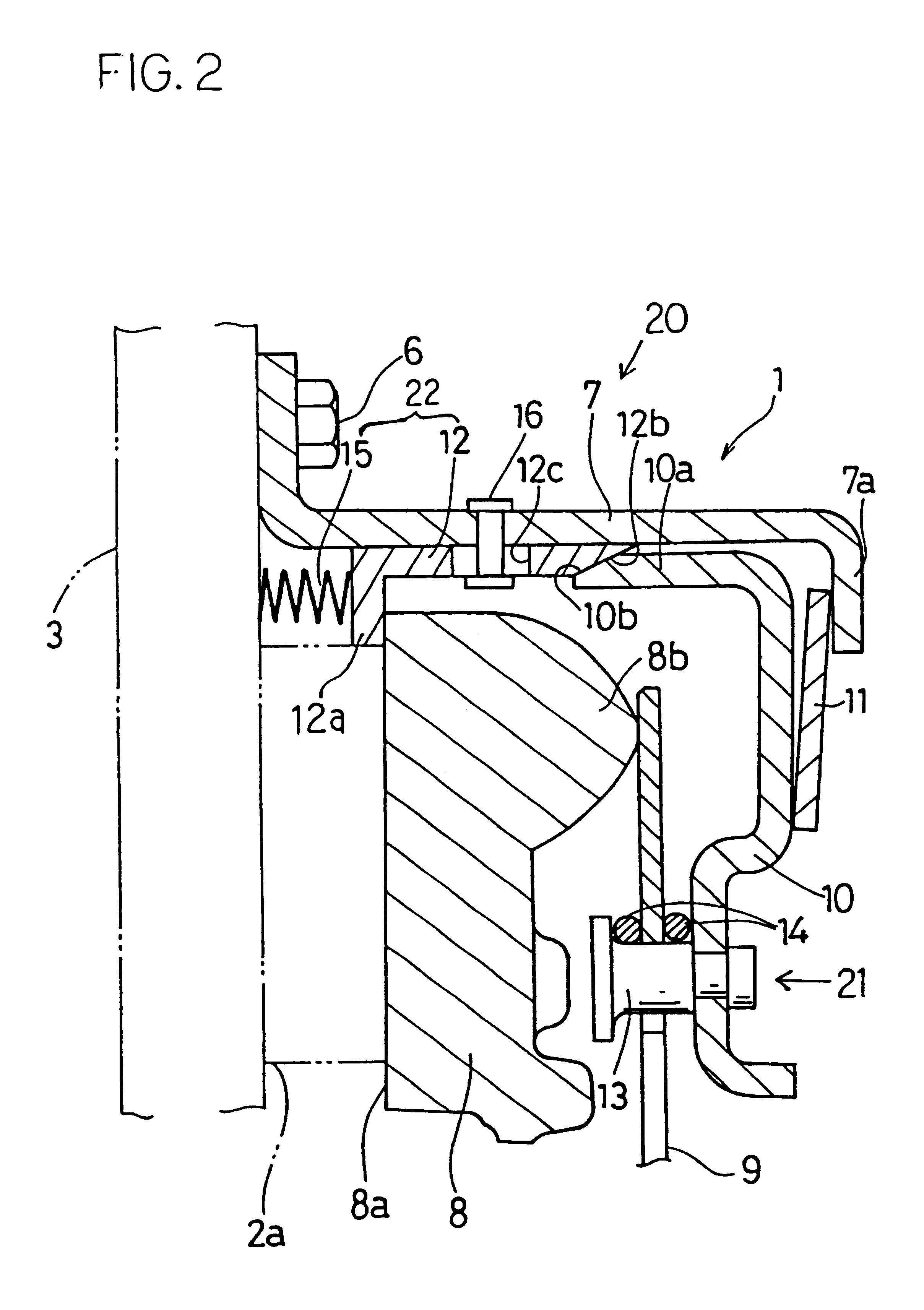
The clutch cover assembly 1 comprises, as shown in FIG. 2, a first clutch cover 7 fixed to the flywheel 3 by bolts 6, a pressure plate 8 located within the first clutch cover 7, a diaphragm spring 9 for pressing the pressure plate 8 toward the flywheel 3, a support mechanism 21 for supporting the diaphragm spring 9, and a movement regulation mechanism 20 for moving the support mechanism 21 toward the flywheel 3 according to the displacement due to wear on facings ...

second embodiment

A clutch cover assembly 31 shown in FIG. 4 is used in a push-type clutch as in the first embodiment. The clutch cover assembly 31 mainly comprises a clutch cover 37 fixed to a flywheel 33 of the engine (not shown), a pressure plate 38 located within the clutch cover 37, a diaphragm spring 39 for pressing the pressure plate 38 toward the flywheel 33, a support mechanism 41 for supporting the diaphragm spring 39, and a movement regulation mechanism 51 for moving the support mechanism 41 toward the facings 32a according to the wear amount of the facings 32a of the clutch disc assembly (not shown).

The clutch cover 37 has a disc portion with an inclined surface 37a approaching the pressure plate 38 as its goes radially outward.

The pressure plate 38 is generally annular, and is formed with a lateral pressing surface 38a for pressing the facing 32a against the flywheel 33. Formed on the opposite lateral side of the pressure plate 38 are extensions 38b that extend axially. Integrally formed...

third embodiment

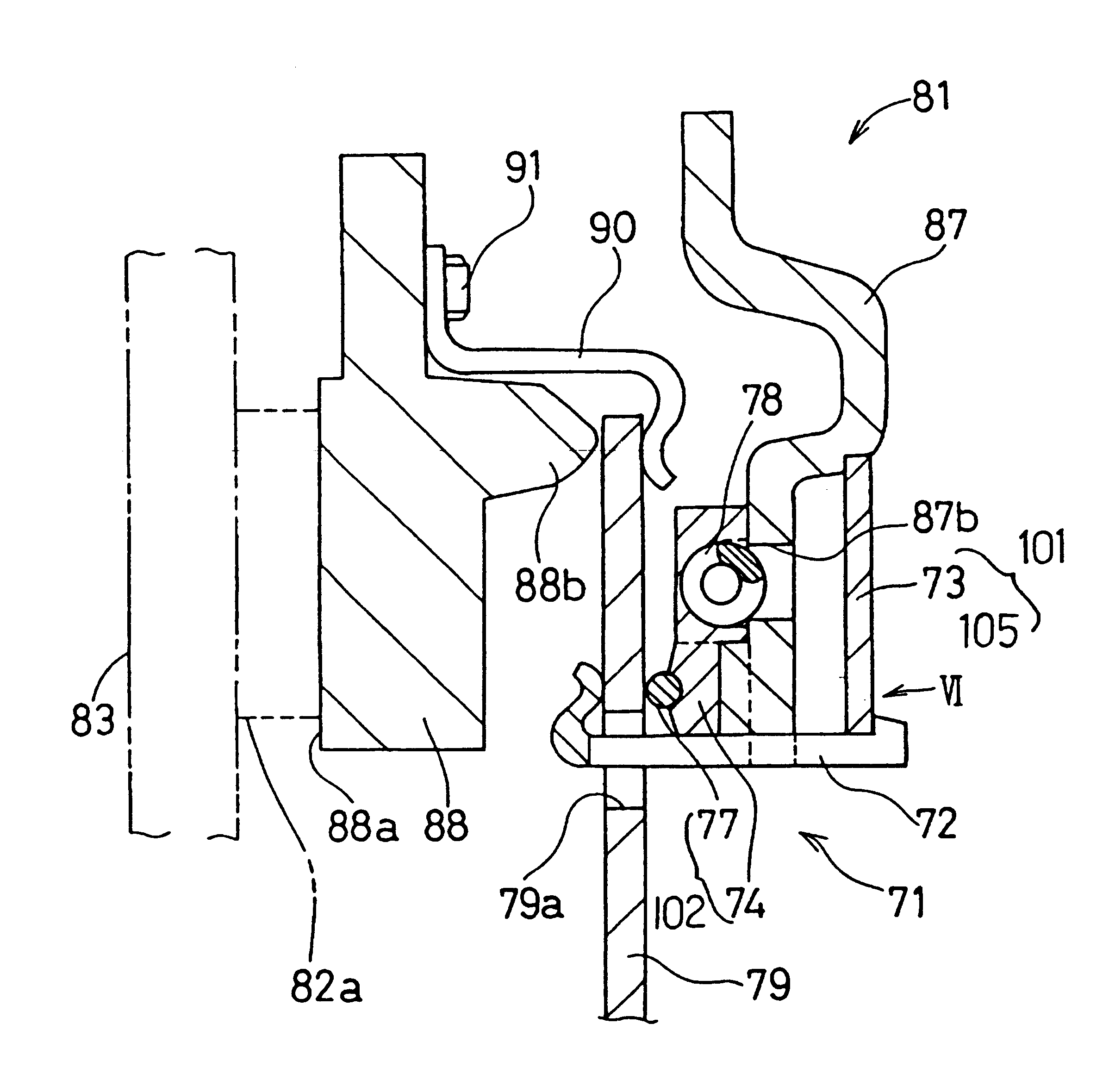
A clutch cover assembly 81 shown in FIG. 5 is employed in a push-type clutch like the first and the second embodiments, and comprises a clutch cover 87 fixed to the flywheel 83 of the engine, a pressure plate 88 located in the clutch cover 87, a diaphragm spring 79 for pressing the pressure plate 88 toward the flywheel 83, and a support mechanism 71 for supporting the diaphragm spring 79, and a movement regulation mechanism 101 for moving the support mechanism 71 toward the facings 82a according to wear of the facings 82a of a clutch disc assembly (not shown).

The pressure plate 88 is generally annular and is provided with a pressing surface 88a for clamping the facings 82a of the clutch disc assembly between the flywheel 83 and itself. The pressure plate 88 is formed with annular projections 88b projecting in the axial direction on the diaphragm spring 79 side. The pressure plate 88 is fixed to the clutch cover 87 through strap plates (not shown) so as to be movable in the axial dir...


PUM


Abstract

A clutch cover assembly is used for urging a friction member connected to an output member against an input rotation member and for releasing urging on the input rotation member. The clutch cover assembly comprises a clutch cover, a pressure plate, an urging member, a support mechanism and a movement regulation mechanism. The clutch cover is fixed to the input rotation member. The pressure plate is located within the clutch cover and urges the friction member. The urging member urges the pressure plate toward the friction member. The support mechanism is movable toward the friction member and supports the urging member. The movement regulation mechanism moves the support member toward the friction member according to wear displacement of the friction member.

Description

BACKGROUND OF THE INVENTIONThe present invention relates to a clutch cover assembly, particularly to a clutch cover assembly with a mechanism for keeping a pressing load constant by compensating for the wear on the friction members.A clutch cover assembly is, generally, fixed to a flywheel of the engine and presses friction members of the clutch disc assembly against the flywheel in order to transmit the power of the engine to the transmission. Excessive wear on the friction members shortens the lives of the clutch disc assembly and the clutch disc assembly. It is possible to lengthen life of the clutch disc assembly by increasing effective thickness of friction members. For example, by attaching facings to the cushioning plate without using rivets.The clutch cover assembly disclosed in Japanese Patent Laying-Open No. 27092 / 1998 maintains the pressing load of the diaphragm spring at its initial value as facings wear. This clutch cover assembly is shown in FIG. 10 and has a pressure ...

Claims


Application Information

Patent Timeline
Patent Type & Authority Patents(United States)
IPC IPC(8): F16D13/58F16D13/71
CPCF16D13/585F16D13/71
Inventor MIZUKAMI, HIROSHIUENOHARA, NORIHISATAKEUCHI, HIROSHI
Owner EXEDY CORP
Why Eureka
Try Eureka