Stackable pallet

Inactive Publication Date: 2003-04-15
LOCK NEST
View PDF12 Cites 27 Cited by
  • Summary
  • Abstract
  • Description
  • Claims
  • Application Information

AI Technical Summary

Benefits of technology

The present invention is designed to overcome the deficiencies of the prior art discussed above. It is an object

Problems solved by technology

Accordingly, when a similarly collapsed platform is stacked on top of an adjacent collapsed platform, the end walls of the lower platform frequently interfere with the proper alignment of the upper platform which is positioned on top of the same.
Another problem which typically arises when stacking a plurality of planar platforms on top of one another, whether or not they have end wall

Method used


Image

  • Stackable pallet
  • Stackable pallet
  • Stackable pallet

Examples


Example

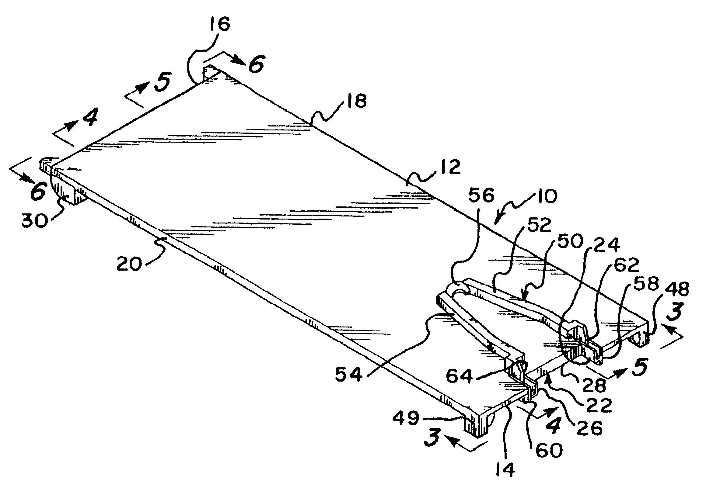
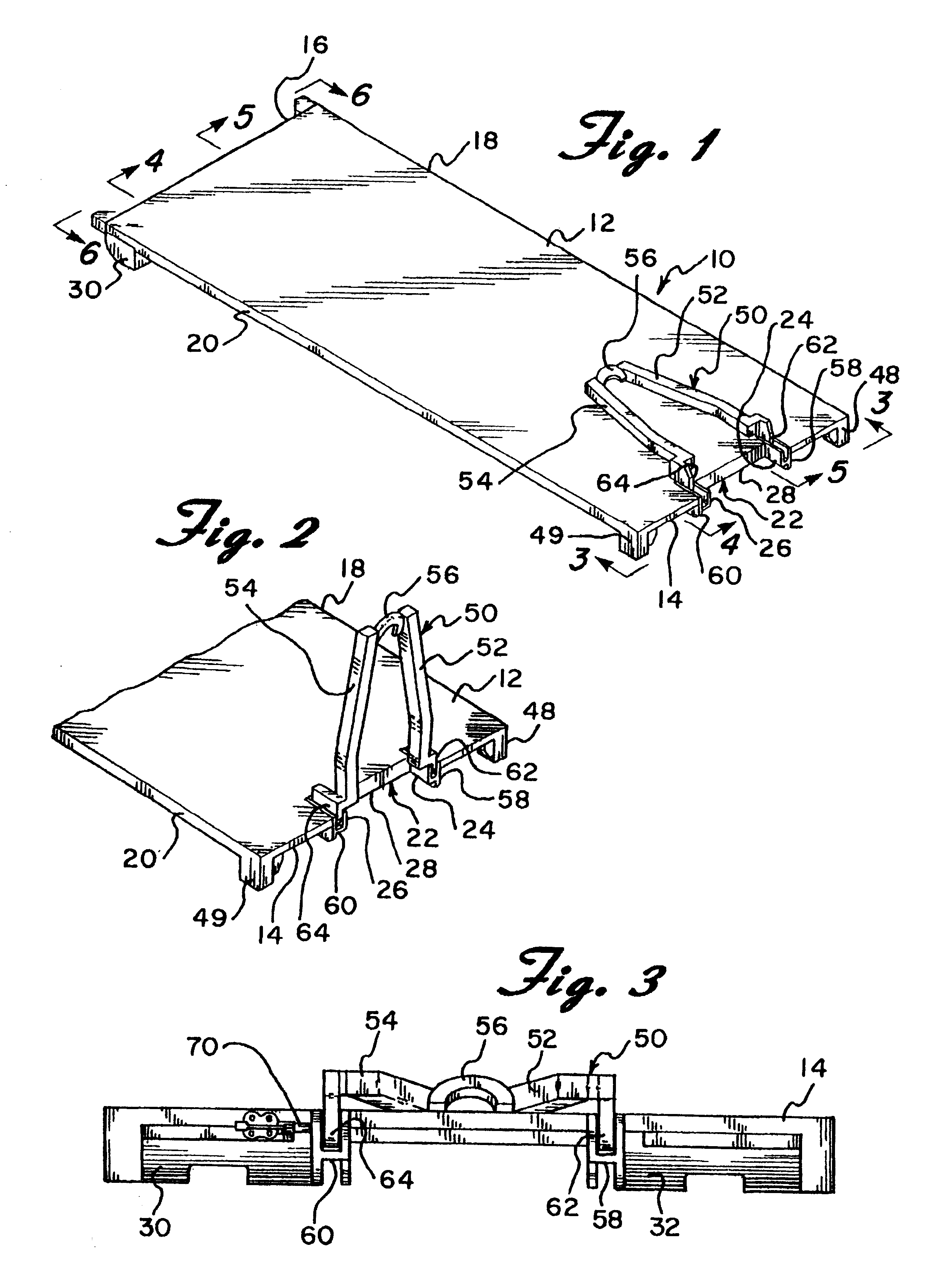
Referring now to the drawings in detail wherein like reference numerals have been used throughout the various figures to designate like elements, there is shown in FIG. 1 a stackable pallet constructed in accordance with the principles of the present invention and designated generally as 10.

The stackable pallet 10 includes a rectangular planar base member 12 which, as can clearly be seen in the figures, has a width and a length. The base member has a first end 14, a second end 16, and two opposing sides 18 and 20. Extending into the first end 14 of the base member 12 is a recess 22. The recess 22 is defined by two side edges 24 and 26 and a transverse edge 28. The base member 12 is preferably about 585 cm long, 230 cm wide, and 12.5 cm high.

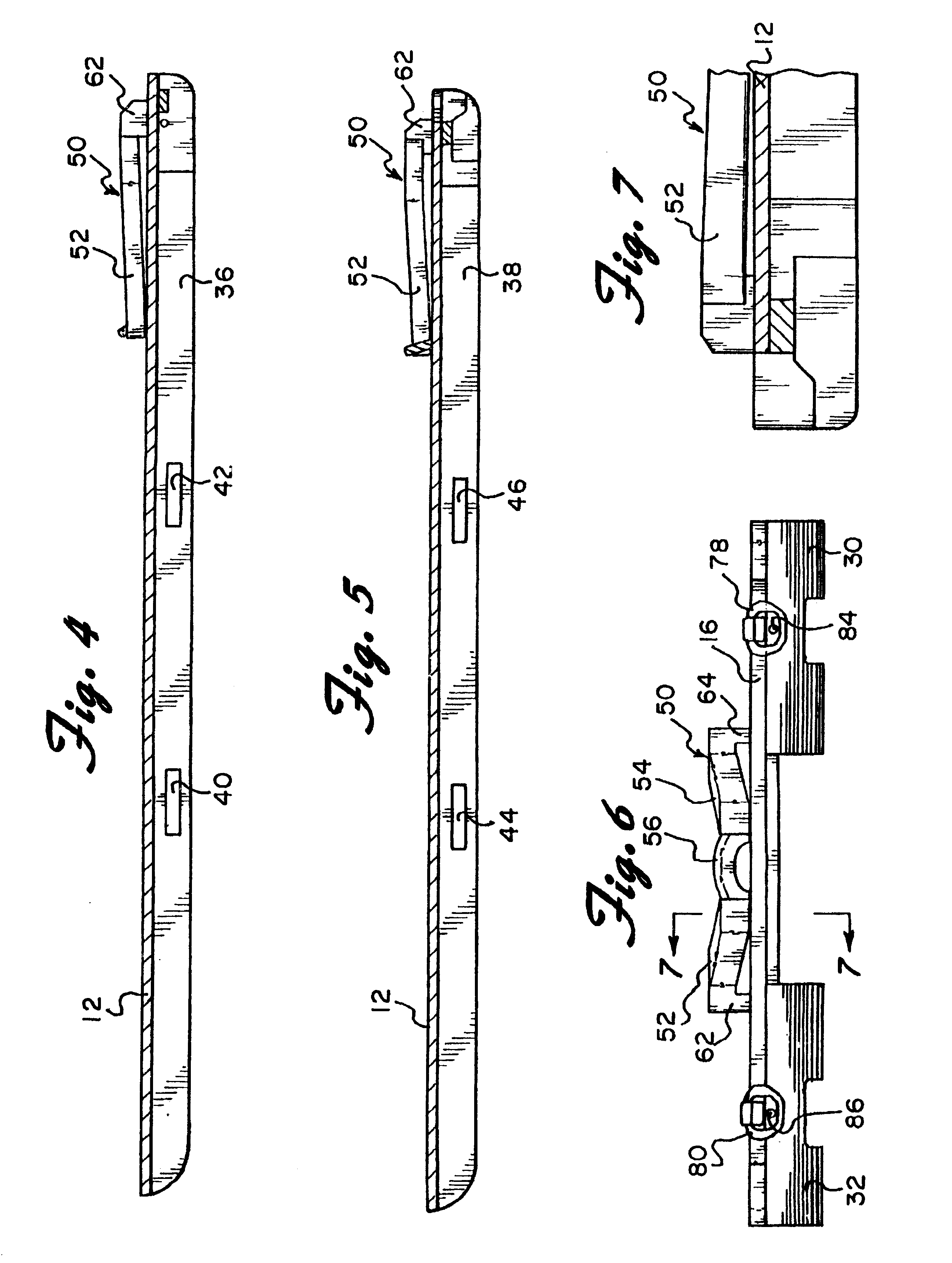
Slider pads in the form of smooth curved segments 30 and 32 extend downwardly from the bottom of the base member 12 adjacent the second end 16 thereof (FIG. 6). Each slider pad is positioned adjacent a different one of the sides 18 and 20 of the ...


PUM


Abstract

A stackable pallet comprises a rectangular planar base member which has two opposing ends and two opposing sides. Extending into one of the ends of the base member is a recess which is defined by two side edges and a transverse edge. A pair of smooth curved members extend downwardly from the other end of the base member. A pair of spaced apart elongated beams extend downwardly from the base member between the ends of the same. A handle member is pivotally secured to the base member between the side edges of the recess. The handle member is adapted to be pivoted from an inoperative position, wherein the handle member is folded on top of the base member, to an operative position, wherein the handle member extends upwardly from the base member.

Description

BACKGROUND OF THE INVENTIONThe present invention is directed toward a stackable pallet and, more particularly, to such a pallet which is adapted to be inserted into an open end of a shipping container and which can be compactly stacked on top of an adjacent pallet when not in use.In order to transport a plurality of packaged goods it is common to first place the goods on top of an article supporting platform or pallet which includes a substantially planar support surface. Such pallets are required to comply with I.S.O. Standards promulgated by the International Standards Organization. U.S. Pat. No. 4,834,000 shows an example of that kind of pallet. Once the pallet is loaded, it is pushed or pulled into a shipping container to be carried by a truck, ship, train or plane. Such pallets are typically rather large and are adapted to support loads of several tons. Accordingly, specialized loading vehicles, e.g. PLS (pallet load and unload system) trucks, are utilized to either push or pul...

Claims


Application Information

Patent Timeline
IPC IPC(8): B65D88/12B65D90/18B65D90/00B65D88/02B65D88/00B65D19/00B65D19/38B65D90/12B65D19/26
CPCB65D19/0026B65D19/0028B65D19/38B65D88/022B65D88/129B65D90/0033B65D90/18B65D2519/00024B65D2519/00059B65D2519/00273B65D2519/00288B65D2519/00323B65D2519/00333B65D2519/00338B65D2519/00557B65D2519/00781B65D2519/00786B65D2519/00791B65D2519/0096
Inventor BRENNAN, JR., JAMES F.CLIVE-SMITH, MARTIN
Owner LOCK NEST
Why Eureka
Try Eureka