Dual-function locks and sub-assemblies therefor

Inactive Publication Date: 2005-10-18
THWING RANDY L
View PDF29 Cites 12 Cited by
  • Summary
  • Abstract
  • Description
  • Claims
  • Application Information

AI Technical Summary

Benefits of technology

[0018]Still another advantage of the present invention is that the inventive lock sub-assembly can be utilized to easily retrofit a variety of locks presently in inventory or actual use. Specifically, in accordance with the present invention, dual-function rotator bolts can be crafted to the dimensions of conventional rotator bolts, thereby permitting replacement of conventional rotator bolts with dual-function rotator bolts. Such substitution, thus, offers still greater versatility in the lock art.
[0019]Finally, other embodiments of the present invention encompass dual5 function locks which utilize the inventive lock sub-assemblies briefly noted above. While such locks are preferably dual-function padlocks, the present invention is not so limited. In particular, the present invention offers significant advantages when utilized in locks with removable cylinder mechanisms whether they be used in door knobs or padlocks. Similarly, specialized cylinder configurations can also be accommodated with the present invention.

Problems solved by technology

However, none of the dual-function padlocks of the related art can be converted between key-retaining and non-key-retaining functions (i.e., inter1 function lock conversion) without the introduction of and / or the disposal of additional lock components.

Method used


Image

  • Dual-function locks and sub-assemblies therefor
  • Dual-function locks and sub-assemblies therefor
  • Dual-function locks and sub-assemblies therefor

Examples


Embodiment Construction

[0041]Dual-function locks, and lock sub-assemblies therefor, in accordance with the preferred embodiments of the present invention will be described with joint reference to the Figures. Throughout this description, however, it is to be understood that, to facilitate understanding of the drawings, only enough structure of the apparatus has been illustrated to enable one skilled in the art to readily understand the underlying principles and concepts of the invention.

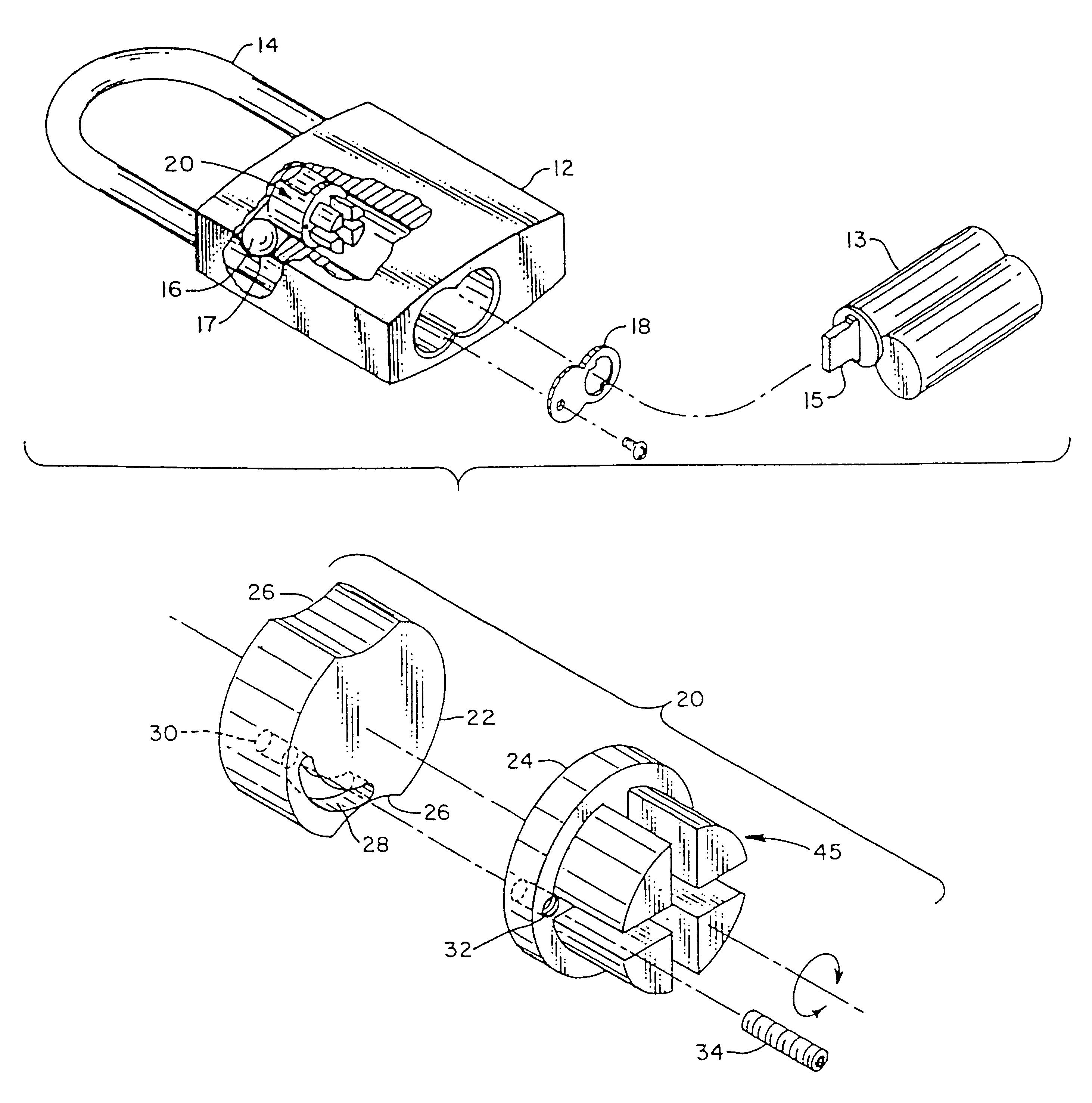
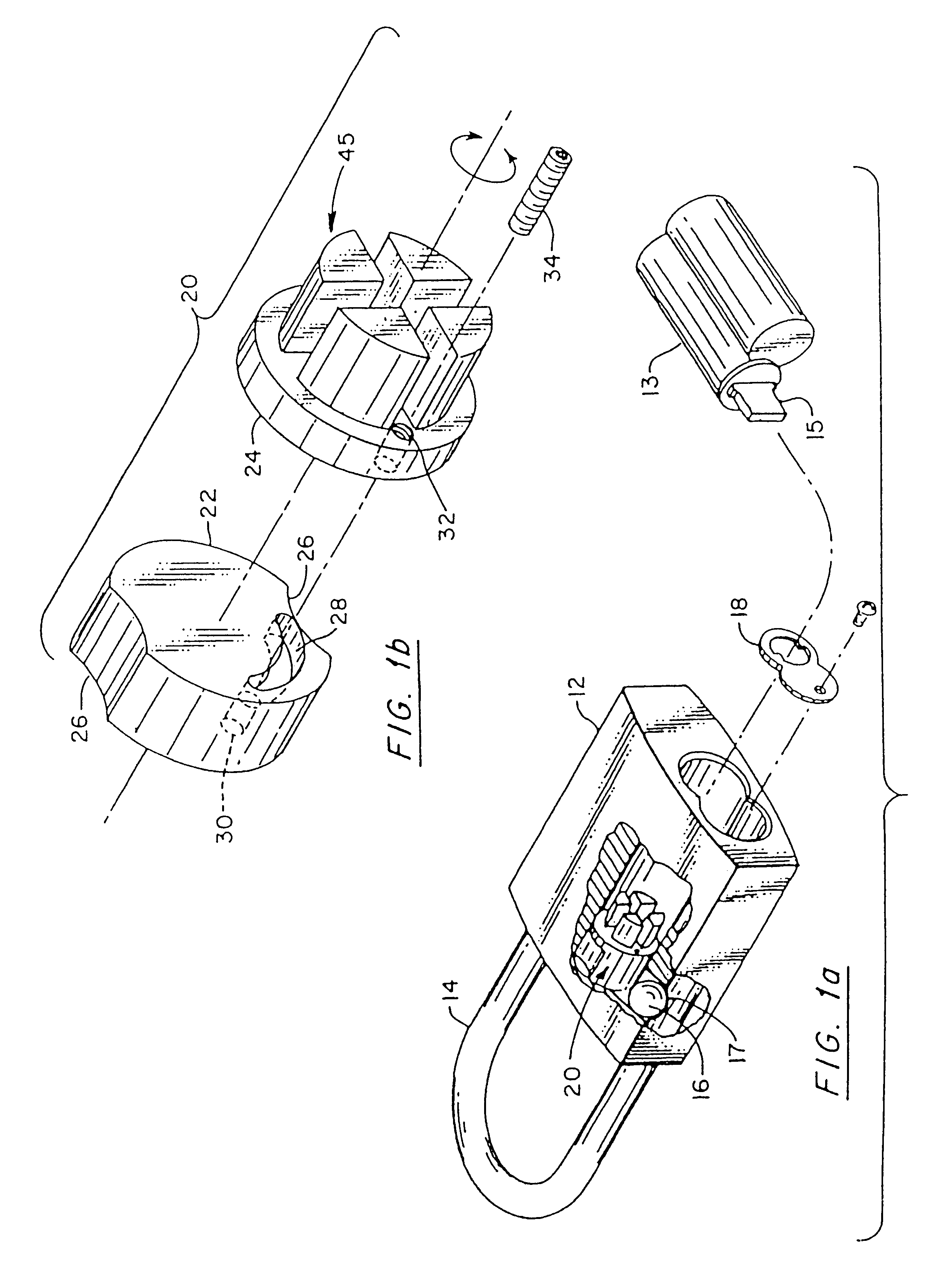
[0042]As shown in FIG. 1a, a dual-function padlock 10 preferably comprises a padlock body 12, a lock cylinder 13 with a blade-like actuator 15 extending therefrom, at least one locking ball 16, a shackle 14 with a recess 17 for selectively receiving ball 16, a rotational stop member 18 with an affixation screw and a lock sub-assembly 20. As shown, padlock 10 is of a generally conventional configuration and employs locking ball 16 as a release / locking mechanism to selectively release retain shackle 14 in a locked condition....


PUM


Abstract

A dual-function lock in accordance with the invention has an axis-defining lock sub-assembly including first and second axially aligned rotator members having confronting first end faces and oppositely facing second end faces. The sub-assembly has a lost-motion recess and an anchor recess on one confronting face and one recess-engaging member extending from another confronting face to permit lock function selection by placing the recess-engaging member into a particular recess. Alternative dual-function lock sub-assemblies include a unitary rotator bolt and a companion actuator. The rotator bolt has a release-mechanism-engaging portion and an actuator-engaging portion. While a first section of the actuator-engaging portion permits limited lost-motion between the rotator bolt and a companion actuator, a second section prevents lost-motion. The lock function can be selectively determined by placing the companion actuator into the desired first or second section of the actuator-engaging portion.

Description

BACKGROUND OF THE INVENTION[0001]1. Field of the Invention[0002]The present invention generally relates to the field of key operated locks. More particularly, the present invention is directed to locks, and subassemblies therefor, which can be converted between key-retaining and non-key-retaining functions. Accordingly, the general objects of the present invention are to provide novel and improved methods and apparatus of such character.[0003]2. Description of the Related Art[0004]Key operated locks are broadly classified into two mutually exclusive lock types. Locks of the first type are known as key-retaining locks because in such locks the lock mechanism prevents the key from being removed from the lock while the lock is in an unlocked condition. Locks of the second type are known as non-key-retaining locks because in such locks the lock mechanism permits the key to be removed from the lock while the lock is in the unlocked condition. Most conventional locks only offer one of the...

Claims


Application Information

Patent Timeline
IPC IPC(8): E05B17/00E05B17/04E05B9/08E05B67/00E05B67/24E05B9/00E05B63/00E05B11/00
CPCE05B9/084E05B11/00E05B17/04E05B63/0065E05B67/24Y10T70/7768Y10T70/7661Y10T70/487Y10T70/774Y10T70/7706
Inventor THWING, RANDY L.
Owner THWING RANDY L
Why Eureka
Try Eureka