Eureka AIR delivers breakthrough ideas for toughest innovation challenges, trusted by R&D personnel around the world.

Method of detecting an ignition voltage signal using a pencil ignition coil and preferred use thereof

Inactive Publication Date: 2005-03-17
SIEMENS AG
View PDF3 Cites 0 Cited by
  • Summary
  • Abstract
  • Description
  • Claims
  • Application Information

AI Technical Summary

Benefits of technology

[0006] These and other objects are achieved, according to one formulation of the invention, by a method of detecting an ignition voltage signal generated by a pencil ignition system, whereby the electromagnetic emission by the pencil ignition system is detected capacitively and analyzed to yield an ignition voltage signal. This has an advantage that the signal is picked up in a non-contact manner and without intervention into the design of the pencil ignition system. The electromagnetic emission by an ignition coil in the pencil ignition system is advantageously detected capacitively and analyzed. This has the advantage that the ignition voltage signal is detected exactly at the location that is the source of the ignition voltage for a cylinder. It is particularly advantageous that the electromagnetic emission is detected radially around the ignition coil. This makes it possible to detect a measurement signal having a high amplitude and a high quality, i.e., a signal with the least possible distortion due to outside influences.
[0009] In a first embodiment, the pickup is configured to be placed over the neck piece of the pencil ignition system. This has the advantage that the pickup of the measurement arrangement can easily be retrofitted as an exterior component. In another embodiment, the pickup is integrated directly into the neck piece. It is then preferably arranged on the inside of the jacket of the neck piece and directly surrounds the ignition coil. Although this configuration requires structural adaptation of the pencil ignition system, it renders possible a high-quality ignition voltage signal that is particularly free of interference.

Problems solved by technology

However, there is the disadvantage that the lack of cabling does not allow ignition voltage signals to be picked up for diagnostic and service purposes.
In addition, another disadvantage with respect to detecting ignition voltage signals is that access to such pencil ignition systems is difficult, e.g. in newer engine designs and in particular in engines having a large number of cylinders.

Method used


Image

  • Method of detecting an ignition voltage signal using a pencil ignition coil and preferred use thereof
  • Method of detecting an ignition voltage signal using a pencil ignition coil and preferred use thereof

Examples


Embodiment Construction

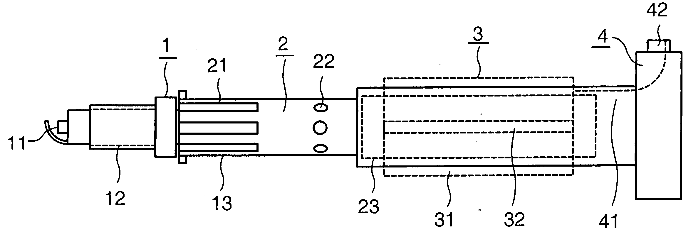
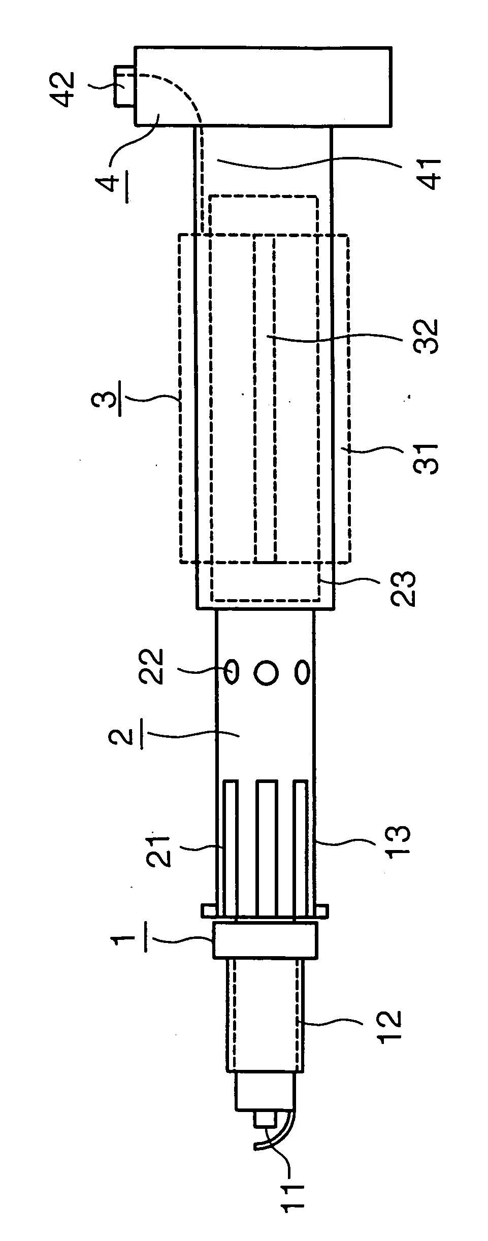
[0014]FIG. 1 shows a pencil ignition system having a spark plug 1 which is situated at the left end of the configuration in FIG. 1 and has, inter alia, an ignition electrode 11, a screw-in thread 12 for mounting the entire configuration in an engine block and a spark plug neck 13 having an insulator and a voltage contact. The spark plug neck 13 is inserted into a plug part 2 which is used for mechanical accommodation and electric contacting of the spark plug 1. The ceramic insulator on the spark plug neck 13 is held by clamping means 21. Electrical contact means 22 are provided directly at the transition point between the spark plug 1 and an ignition coil 23.

[0015] The ignition coil 23 is integrated into a sleeve-shaped neck piece 3, which is shown with dotted lines, in the embodiment of FIG. 1. According to an advantageous embodiment of this invention, the pickup 31 for the ignition voltage signal is designed as a curved cylindrical insulated copper foil. According to this embodim...


PUM


Abstract

A method in which the electromagnetic radiation emitted by the pencil ignition system is detected capacitively and analyzed to yield an ignition voltage signal. Preferably, it is the radiation emitted by an ignition coil in the pencil ignition system that is detected capacitively and analyzed. The radiation is especially advantageously detected radially around the ignition coil. This permits detection of a measurement signal having a high amplitude and high quality. An associated pencil ignition system has a pencil-shaped arrangement of a spark plug (1) mounted on a neck piece (3) with an integrated ignition coil (23), and a measurement arrangement for an ignition voltage signal having a pickup (31) which at least partially surrounds the ignition coil (23) and is made of an electrically conducting material. The pencil ignition system preferably further includes a head part (4) with a connector plug (42) for external control signal lines and power supply lines, as well as a measurement signal line (41) for the ignition voltage signal extending from the pickup (31) to the connector plug (42). The ignition voltage signal can thereby be relayed, e.g., to an electronic analyzer, without the need for any additional cabling, by relaying the signal, e.g. over a cable harness electrically connected to the connector plug, e.g., by way of a mating plug.

Description

[0001] The following disclosure is based on German Patent Application No. 10342533.0, filed on Sep. 12, 2003, which is incorporated into this application by reference. FIELD OF AND BACKGROUND OF THE INVENTION [0002] The present invention relates to a method of detecting an ignition voltage signal generated by a pencil ignition coil and preferred embodiments for a pencil ignition coil having a corresponding design. This invention also relates to a preferred use of such a pencil ignition coil. [0003] Conventional ignition systems, used for internal combustion engines in particular, have a central ignition coil and a distributor. For transmission of the ignition voltages created by this system for the spark plugs of the individual cylinders, there are ignition cables leading to the respective spark plugs. Such an ignition system offers a variety of possibilities for picking up signals, e.g., with the help of measurement tongs, so-called ignition harnesses and / or via plates mounted on t...

Claims


Application Information

Patent Timeline
IPC IPC(8): F02P3/02F02P13/00
CPCF02P13/00F02P3/02
Inventor HEISLBETZ, ROBERT
Owner SIEMENS AG
Why Eureka
Eureka Blog
Learn More