Underwater lighting fixture with color changing electric light assembly

Inactive Publication Date: 2005-08-04
PENTAIR POOL PROD INC
View PDF24 Cites 5 Cited by
  • Summary
  • Abstract
  • Description
  • Claims
  • Application Information

AI Technical Summary

Benefits of technology

[0013] The present invention, which tends to address these needs, resides in a pool lighting system. The pool lighting system described herein provides advantages over known pool lighting systems in that it is less difficult and less costly to install than existing pool lighting systems that can provide a variety of synchronized colors to the pool water and can be easily retrofitted to existing incandescent lighting systems.

Problems solved by technology

However, fiber optic underwater illumination systems have several limitations that lead to the need for the present invention.
The availability of qualified training is limited thus the availability of trained installers is limited.
Rushed fiber termination or fiber termination performed by an untrained installer can result in more than a 30% decrease in fiber optic system performance and can ultimately result in a costly failure of the total fiber optic system.
The second disadvantage of underwater fiber optic illumination is the limited amount of light delivered to the pool.
This results from the light attenuation over distance that is inherent in the fibers' composition and the inefficiencies of focusing available light into the optical fiber at the light source.
A further drawback of fiber optic underwater illumination is in the possibility of retrofitting the millions of existing pools having traditional submersible incandescent lighting fixtures.
The feasibility of installing adequately sized fiber optic cable in the existing conduits is limited.
An additional limitation of fiber optic systems is the additional cost of the materials and professional installation.
The alternative to colored fiber optic systems, providing colored lenses to submersible incandescent lighting fixtures, can be troublesome as well.
These colored glass lenses are typically limited to how richly they can color the light because the darker (or richer) the lens color, the more light in the form of heat that is trapped in the lens and the fixture.
As the lens becomes too hot by absorbing too much light it can break due to thermal expansion or due to the differences in thermal expansion on the hot interior surface of the glass and the cool exterior surface that is in contact with the water.
Further, as a result less light is emitted and it may be insufficient to illuminate the pool.
Economical transparent colored plastics are also inefficient light transmitters reducing the amount of colored light reaching the pool.

Method used


Image

  • Underwater lighting fixture with color changing electric light assembly
  • Underwater lighting fixture with color changing electric light assembly
  • Underwater lighting fixture with color changing electric light assembly

Examples


Embodiment Construction

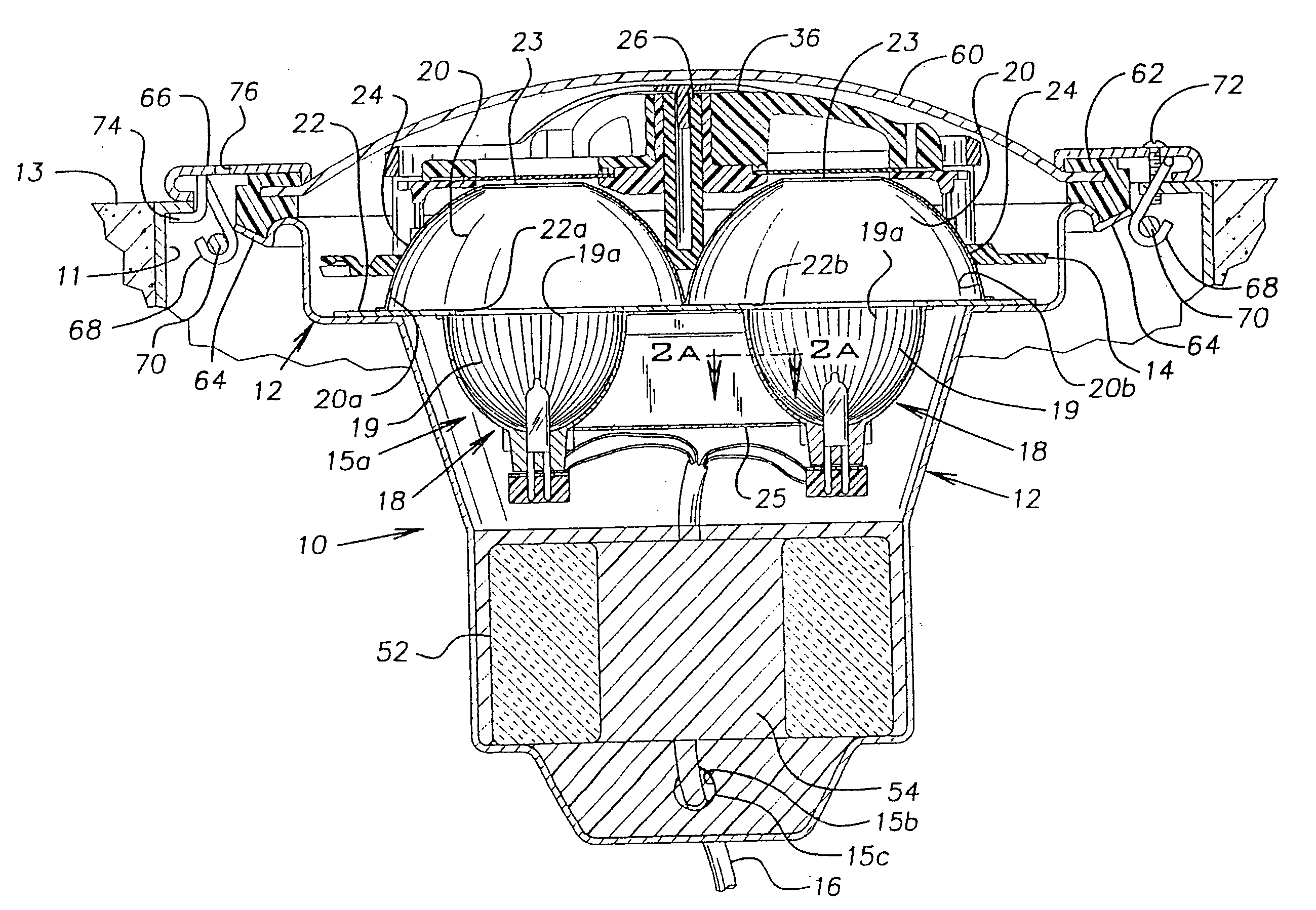
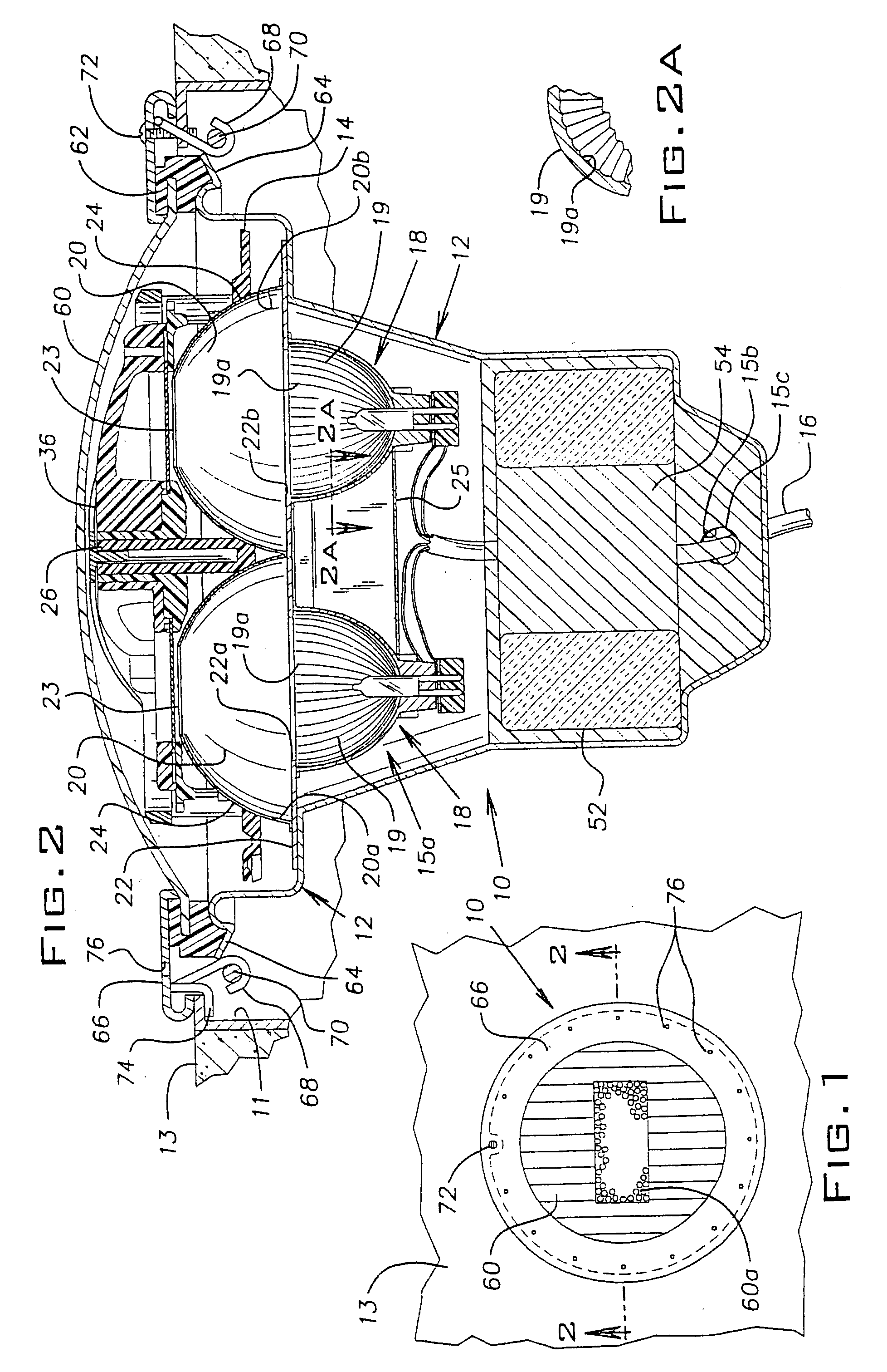
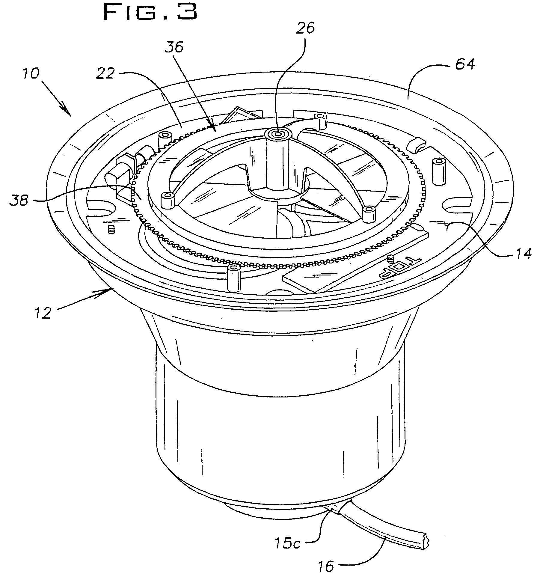
[0026] As shown in the drawings, and with particular reference to FIGS. 1 and 2, the present invention is embodied in a submersible incandescent lighting fixture 10 comprising a housing 12 having an open mouth 15 and defining a cavity 15a with a rear opening 15b. A component tray 14 is mounted on the housing 12. The lighting fixture 10 is adapted to be mounted in a recess 11 in a wall 13 of a pool. A power cord 16 extends from the housing 12 through the opening 15b and is sealed by a grommet 15c to provide power to the lighting fixture 10.

[0027] Referring to FIG. 2, to provide light to a pool, the lighting fixture 10 further comprises two lamps 18 with integral primary reflectors 19 made of dichroic-coated glass and having axial grooves 19a therein and two secondary reflectors 20 mounted to a copper plate 22, the plate 22 being mounted to the housing 12 and having a pair of diametrically opposed openings 22a and 22b. The secondary reflectors 20 extend through two circular passages ...


PUM


Abstract

An underwater lighting fixture adapted for installation in a wall of a swimming pool. The lighting fixture includes a housing having an interior cavity and a transparent cover. A color changing electric light assembly is provided in the interior cavity. The light assembly emits a plurality of different colors of light through the transparent cover and cycles through the plurality of different colors of light to sequentially emit each of the plurality of different colors of light. An electrical conductor extends through the housing into the interior cavity for delivering power to the color changing electric light assembly. A synchronization circuit responds to a timed interruption in the power for synchronizing the color changing electric light assembly with a color changing electric light assembly of another underwater lighting fixture connected to the same power.

Description

CONTINUITY DATA [0001] The subject application is a division of U.S. application Ser. No. 10 / 844,847 filed on May 13, 2004, which is a continuation of U.S. application Ser. No. 10 / 128,041 filed on Apr. 22, 2002, now U.S. Pat. No. 6,811,286 issued on Nov. 2, 2004, which is a continuation of U.S. application Ser. No. 09 / 540,080 filed on Mar. 31, 2000, now U.S. Pat. No. 6,379,025 issued on Apr. 30, 2002.BACKGROUND OF THE INVENTION [0002] The present invention relates generally to the field of illumination, and, more particularly, to a submersible color light. Although the present invention is subject to a wide range of applications, it is especially suited for use in a pool lighting system, and will be particularly described in that context. [0003] Pool lights illuminate the water at night for the safety of swimmers and for aesthetic purposes. The illumination emanates from underwater lights affixed to the wall of the pool. As used herein, a pool is used generically to refer to a conta...

Claims


Application Information

Patent Timeline
IPC IPC(8): F21S8/00F21S10/00F21S10/02F21V9/40
CPCF21S8/00F21S10/007F21S10/02F21V7/0016F21V7/0025F21V29/89F21V11/08F21V23/02F21V29/004F21W2131/401H05B37/029F21V9/10F21V9/40H05B47/155F21V31/00
Inventor MATEESCU, MICHAEL V.POTUCEK, KEVINBACHMAN, ROBERT
Owner PENTAIR POOL PROD INC
Why Eureka
Try Eureka