Surf- or sail-board and method of producing the same

a technology of sailboards and surfboards, applied in the direction of skis, snowboards, sports apparatus, etc., can solve the problems of not allowing the position of the fin to be corrected, unable to mount the fins with sufficient strength, and unable to ensure a sufficiently secure attachment, so as to reduce the cost of manufacture, reduce the force exerted by the fin attachment on the surfboard, and reduce the strength requirements

Inactive Publication Date: 2005-10-18
RAPP PETER
View PDF23 Cites 20 Cited by
  • Summary
  • Abstract
  • Description
  • Claims
  • Application Information

AI Technical Summary

Benefits of technology

[0017]A screw connection fed through the board from above can be designed to be simple and easily accessible for the user. As a result, the fins can be removed in a simple manner which, for example, considerably facilitates transportation of the board. Furthermore, it is not a problem to exchange the fins in the event of fins of a given size being required for the respectively prevailing conditions of use, and it is likewise simple to exchange the fin quickly in the event of a breakage or the like.
[0018]According to a preferred further development of the invention, the opening through which the fin is screwed is designed as a slot which extends essentially in the longitudinal direction of the board. This design has the particular advantage that the position of the fin can be changed in relation to the sailboard. The slot is preferably designed such that it is completely covered by the fin even if the fin is in an extreme position defined by the ends of the hole. As a result, the fin can be implemented as an adjustable fin which, in contrast to the designs in the abovementioned prior art, does not affect the flow conditions on the underside of the board.
[0019]In particular, but not exclusively in the latter construction shown, the fin is preferably provided with an extension which engages in the slot. This extension has the advantage that it transmits any torque, which occurs during loading of the fin, to the board over a large area, thus avoiding damage to the board and fin.
[0022]According to a second preferred alternative of the method according to the invention, the plastic body is produced in advance, specifically preferably by an injection moulding method. This embodiment of the method according to the invention considerably reduces the expenditure for the manufacture of a surfboard. The injection-moulded moulding is inserted in a suitable manner into the mould for the manufacture of the surfboard and is then foamed in during the manufacturing process. This results in a firm connection between the foam and the moulding.
[0023]By the use of the prefabricated plastic body, the force exerted by the fin attachment on the surfboard is considerably reduced and is essentially absorbed evenly by the foam. As a result, the strength requirements placed on the surfboard are reduced, such that it is possible to manufacture the surfboard without a plastic body. The surfboard then consists only of the corresponding foamed body, which considerably reduces the manufacturing costs. However, in this case it is possible to provide a part of the outer surface of the surfboard, in particular the standing surface for the user, with a plastic covering in order to increase the strength in this region or to achieve specific technical (high friction) or visual (specific colourings) properties.

Problems solved by technology

This therefore causes the problems of mounting the fins on the board with sufficient strength.
However, this type of attachment has the disadvantage that it does not ensure a sufficiently secure attachment, and that it furthermore does not allow the position of the fin to be corrected in relation to the board.
An adaptation of the fin position with regard to different external conditions is thus not possible.
The abovementioned designs have the disadvantage that, on the one hand, they are relatively complicated and that, on the other hand, the strength leaves much to be desired.

Method used


Image

  • Surf- or sail-board and method of producing the same
  • Surf- or sail-board and method of producing the same
  • Surf- or sail-board and method of producing the same

Examples


Embodiment Construction

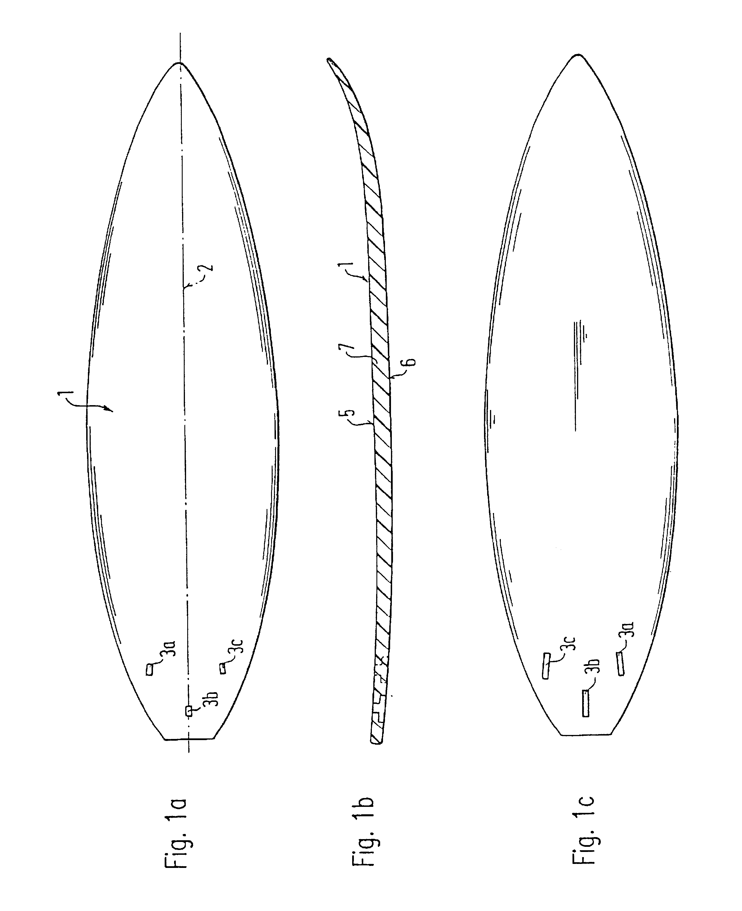
[0039]FIG. 1a shows the top view of a surfboard 1 which is arranged essentially symmetrically to an axis 2 running in the longitudinal direction.

[0040]In the rear region of the surfboard there are three slots 3a, 3b and 3c, the slots 3a and 3c enclosing with their longitudinal axes an acute angle relative to the longitudinal axis 2, while the slot 3b is arranged symmetrically to the longitudinal axis.

[0041]FIG. 1b shows a section through the surfboard according to FIG. 1a, 5 denoting the upper side of the surfboard on which the user stands and 6 denoting the underside which faces the water.

[0042]FIG. 1c shows a bottom view, the slots 3a, 3b and 3c also being visible here.

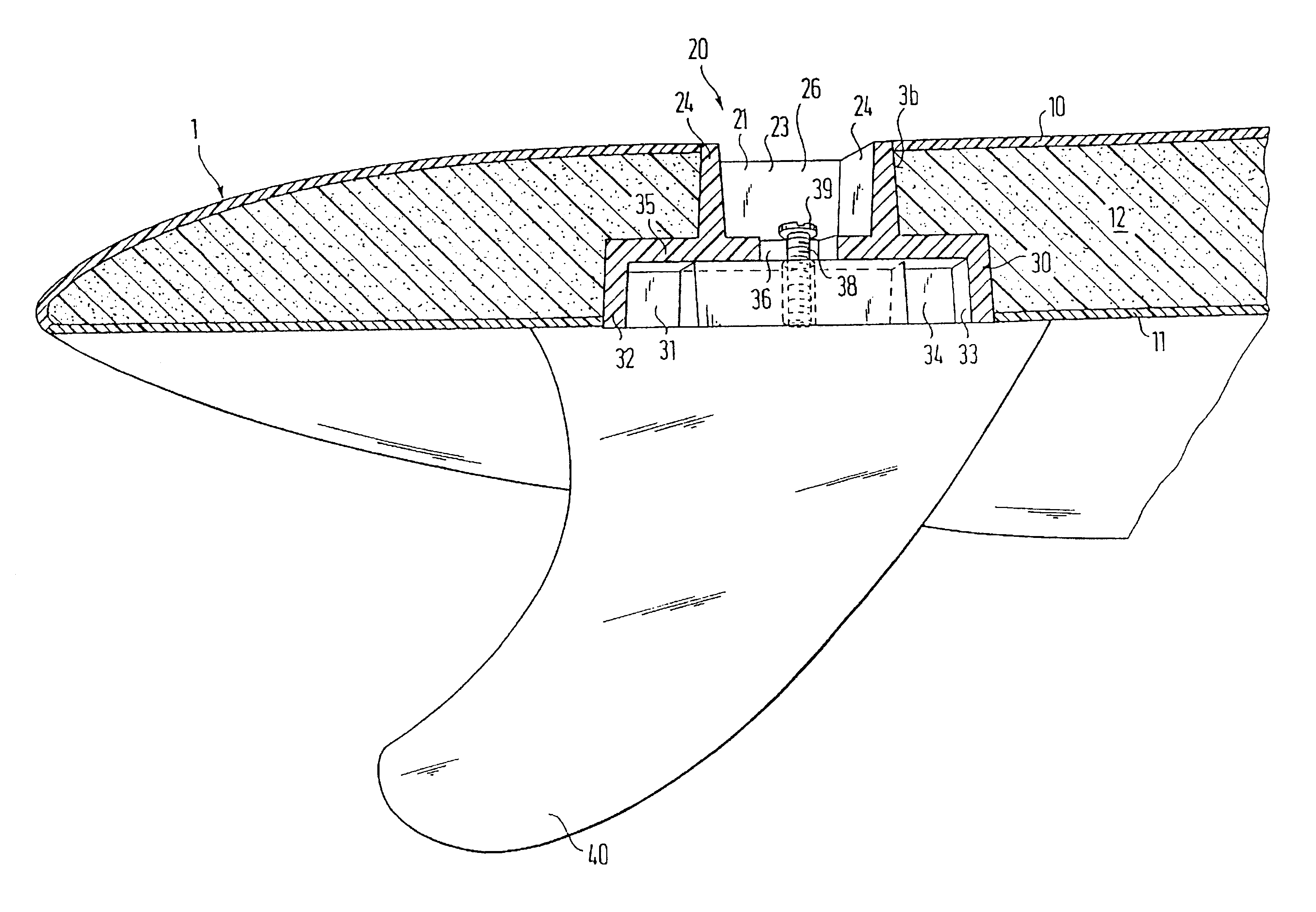
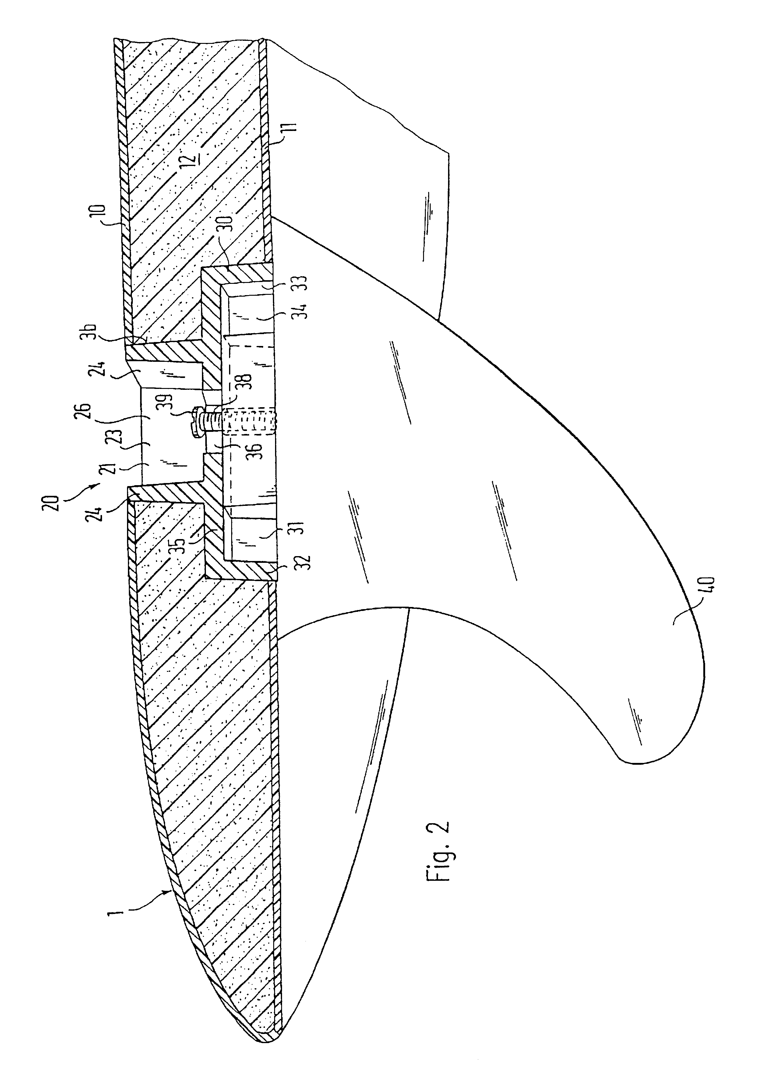
[0043]FIG. 2 shows a section through the surfboard along the axis of symmetry of the slot 3b running in longitudinal directions.

[0044]As can be seen in this section, the surfboard 1 consists of a plastic upper shell 10, a plastic lower shell 11 and a foamed body 12 arranged between them. In the exemplary embodiment,...


PUM


Abstract

Surfboard having an essentially elongate, flat basic body which is capable of floating and, during use, rests with its underside on the water, and on whose upper side there is provided a standing surface for the feet of the sports person using the board, and in which at least one fin is attached to the underside. An opening extending from the underside towards the upper side is provided in the basic body for receiving the said fin, whose extent in the transverse direction of the board, that is to say transversely to the direction of travel and transversely to the surface plane of the fin, is less than the cross-section of the fin; the outer edges of the fin cross-section at the connection point to the board are preferably designed in such a way that the outer edges rest essentially completely against the underside of the board.

Description

FIELD OF THE INVENTION[0001]The present invention relates to a surfboard or sailboard and a method for the manufacture thereof.BACKGROUND OF THE INVENTION AND DESCRIPTION OF RELATED ART[0002]A surfboard is to be understood to mean all customary, essentially flat floating bodies which are suitable for surfing. Sailboards are understood to be the essentially flat floating bodies which are or can be fitted with a sail and are used for windsurfing and the like. For reasons of simplicity, the invention is described below by way of the example of a surfboard for surfing. However, it is pointed out that this does not mean any restriction for the applicability of the invention.[0003]To stabilize the direction, surfboards and sailboards require a so-called fin, a plate which is often of essentially triangular design and whose plane is arranged essentially parallel to the plane of the direction of travel. In addition to the triangular basic shape of the fin, there are numerous modifications, ...

Claims


Application Information

Patent Timeline
Patent Type & Authority Patents(United States)
IPC IPC(8): B63B35/73B63B35/79
CPCB63B32/66
Inventor PATTERSON, COLIN
Owner RAPP PETER
Why Eureka
Try Eureka