Frictionally driven belted work machine

a belted work machine, frictionally driven technology, applied in the direction of conveyors, vehicle maintenance, vehicle cleaning, etc., can solve the problems of lower maximum travel speed, higher initial cost, and high noise levels, and achieve the effect of augmenting the guide apparatus, enhancing the guide apparatus, and maintaining the lateral bel

Inactive Publication Date: 2005-11-01
CATERPILLAR INC
View PDF109 Cites 18 Cited by
  • Summary
  • Abstract
  • Description
  • Claims
  • Application Information

AI Technical Summary

Benefits of technology

[0011]The present invention generally includes a chassis, a pair of longitudinally spaced wheels arranged on each lateral side of the chassis in supporting relation thereto, an endless belt having an elastomeric exterior surface and being highly tensioned to provide frictional coupling between an interior surface thereof and the outer periphery of at least one wheel of each pair, and guide apparatus for maintaining lateral registry between each belt and the associated wheels. The belt tension is regulated by a tensioning apparatus which maintains the frictional coupling, accommodates debris ingestion between the belt and wheels without damaging either, and augments the guide apparatus in maintaining lateral belt to wheel registry. The belts are longitudinally reinforced to permit their high degree of tensioning and are laterally and transversely reinforced to resist movement in those directions and further augment the guide apparatus in retaining lateral registration.

Problems solved by technology

The popularity and nearly universal acceptance of wheel propulsion systems rather than track systems in agricultural use stems primarily from the present day track system's relatively higher noise levels, higher initial cost, lower maximum travel speed, and inability to transport itself on improved road surfaces without inflicting unacceptable damage.
While the noise level and roading problems exhibited by conventional track may be minimized by cushioning the ground engaging surface thereof, commercially unacceptably high wear rates generally occur at the moveable joints between the rigid track sections when such conventional track is used in high speed applications.
Problems encountered in actually reducing such belt system to practice include how to drive such belt with the entrained wheels, how to maintain structural integrity of the belt and wheels, how to retain the belt in lateral alignment with the wheels when the wheels are subjected to large lateral loads, how to provide long life for the belt and wheels, and how to accommodate debris ingestion between the wheels and belt while maintaining the driving relationship therebetween without damaging either.
Limited success has been achieved in providing belt systems for some light duty applications such as snowmobiles.
Attempts to expand the use of belt systems to heavy-duty commercial applications have, in general, met with failure.
The driving slots of such structures tend to accumulate debris which disengages the frictionally engageable side surfaces.
Radial grooves in the walls bounding such slots have been used in attempts to expel debris from the slots but have been generally uneffective.
Solutions to the problems of actually implementing a heavy-duty vehicular belt drive system have proven ellusive and scientific scaling techniques have not, to date, been successfully applied to light duty vehicles for purposes of developing a heavy-duty belt system.
Thus, despite the long felt need for and the advantages thereof, a heavy-duty application vehicle utilizing such belt system is commercially unavailable today.

Method used


Image

  • Frictionally driven belted work machine
  • Frictionally driven belted work machine
  • Frictionally driven belted work machine

Examples


Embodiment Construction

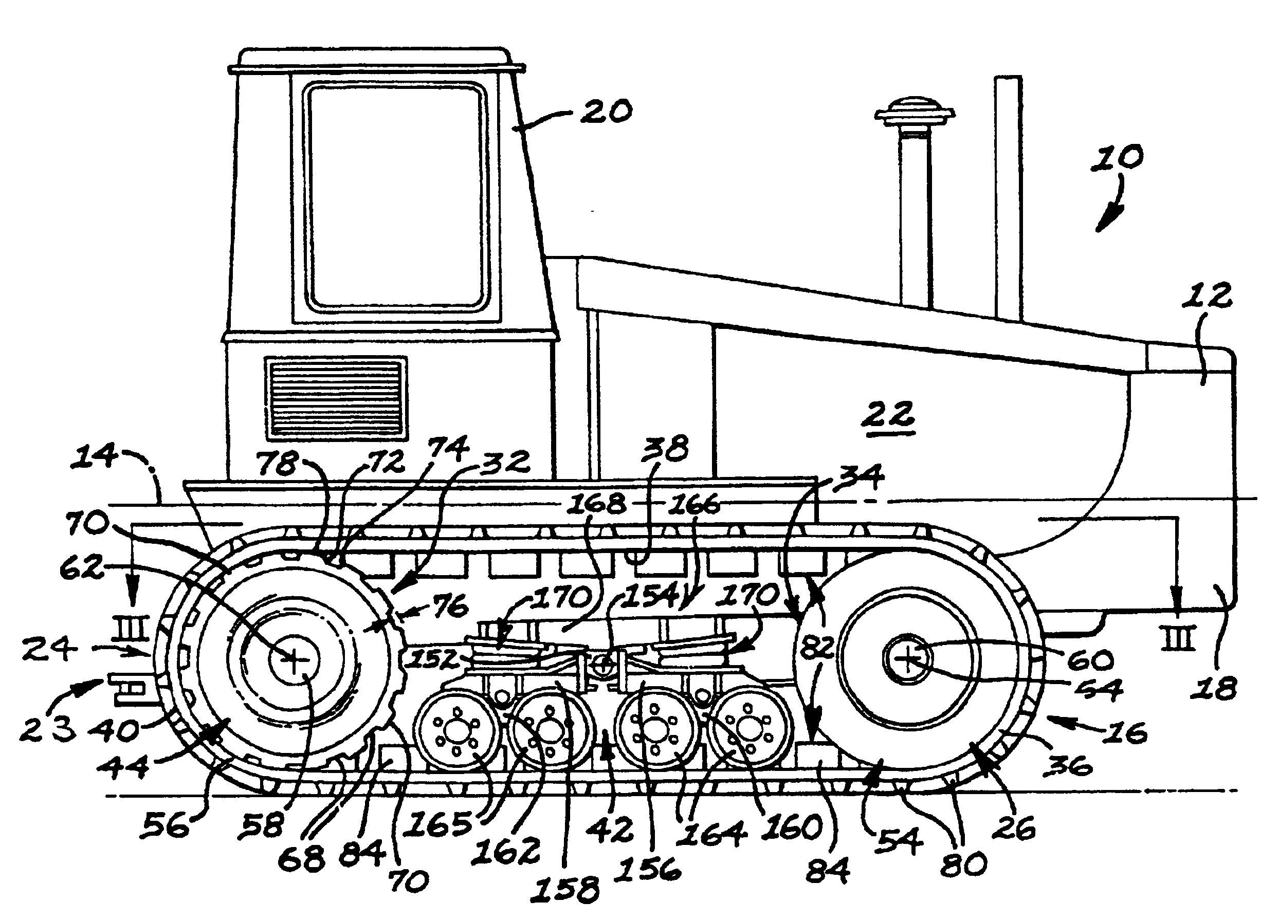
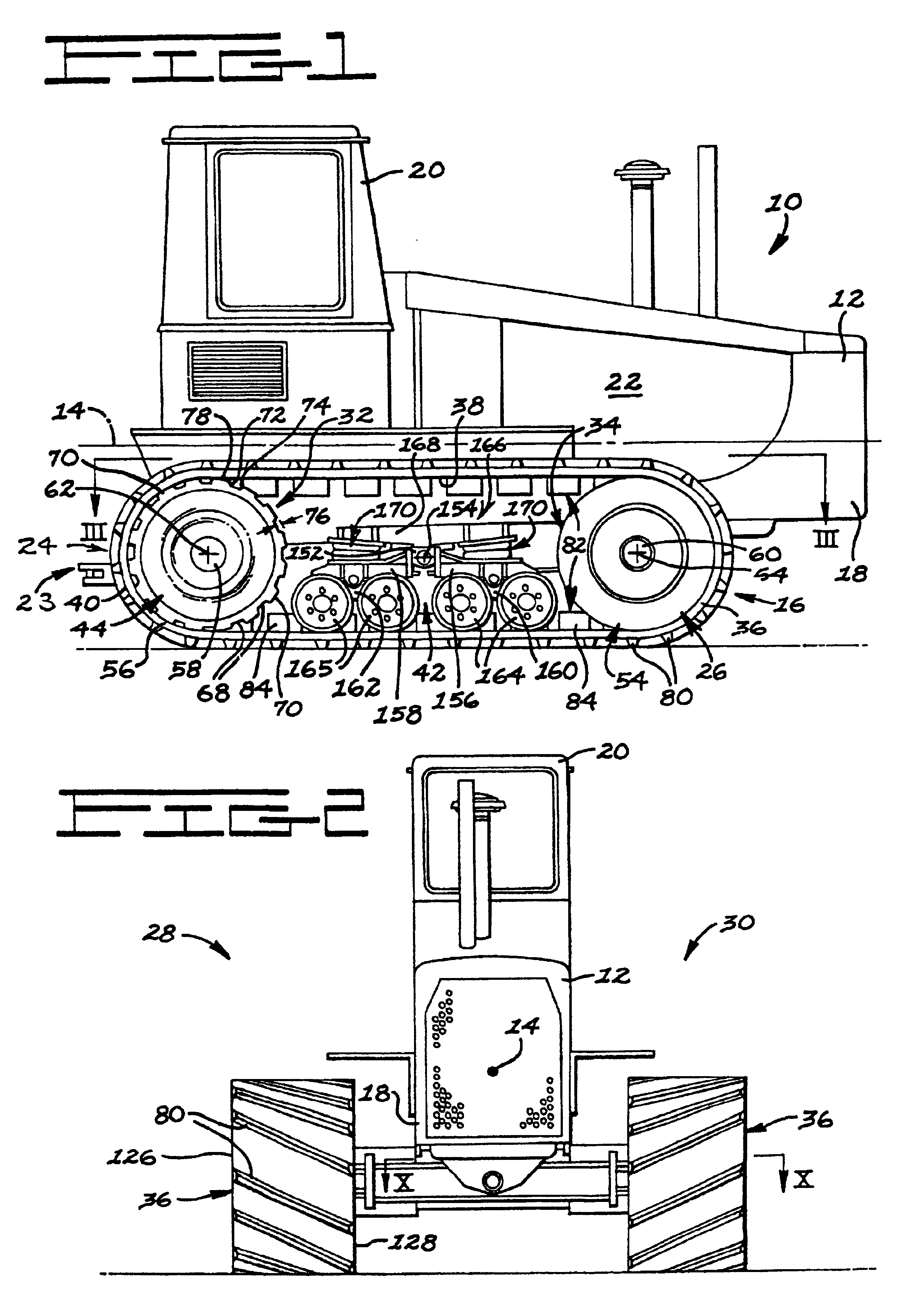
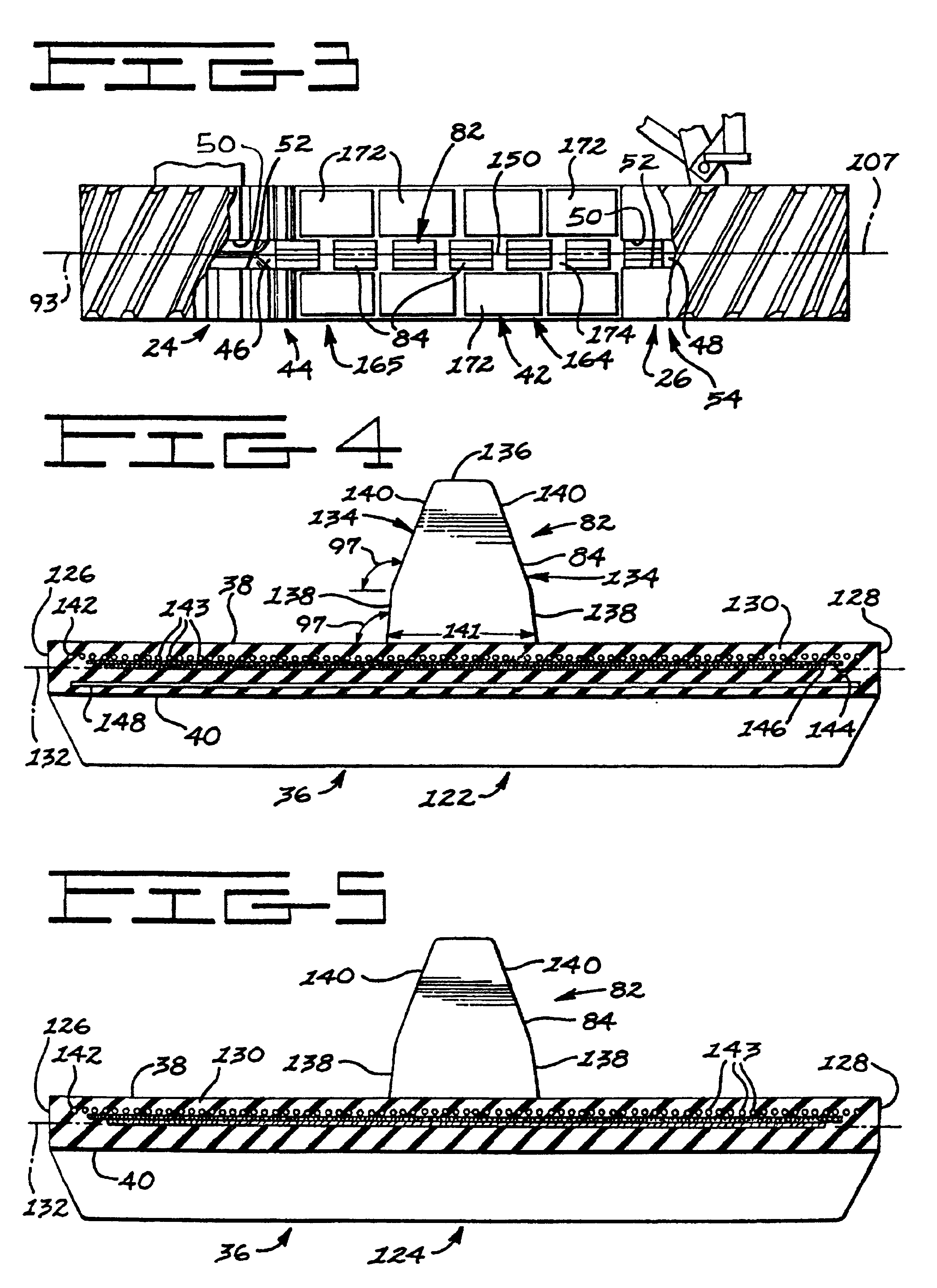
[0026]In general, the greatest problems encountered in providing a belt-over-wheel propulsion system for heavy-duty application are:[0027](1) Maintaining lateral registry between each belt and its entrained wheels when the utilizing vehicle is subjected to high lateral loads;[0028](2) Maintaining a driving relationship between the driver wheel(s) and the entraining belt; and[0029](3) Accommodating debris intrusion between each belt and its entrained wheels without damaging either.

[0030]Solutions to the aforementioned problems will be discussed in conjunction with the structure providing such solutions.

[0031]Referring now to the drawings in detail, FIG. 1 illustrates an exemplary belt laying work vehicle 10 having a chassis 12 with a longitudinal axis 14 and a propulsion system 16 which resides generally beneath and in supporting relation to a frame 18 which, together with an operator's station 20 and an engine 22, constitutes the chassis 12. A rearwardly protruding drawbar 23 is joi...


PUM


Abstract

An elastomeric belt laying vehicle is disclosed for transmitting greater tractive effort to the earth as compared to comparably powered wheel vehicles and being operable at high speed on improved road surfaces without inflicting damage thereto. A pair of the wheels are arranged on each lateral side of the vehicle's chassis for support thereof. An inextensible, endless belt is highly tensioned throughout its length, is entrained about each pair of wheels, and is frictionally, drivingly coupled to at least one wheel of each pair. The structure of the belt, structure of the wheels and cooperating components thereof ensure engagement therebetween, provides long service with minimum maintenance thereof, and supplies the necessary frictional couple to effectively transmit driving torque from the wheels to the belt.

Description

CROSS REFERENCE TO RELATED APPLICATION[0001]This application is a continuing reissue application of reissue application Ser. No. 08 / 674,423 filed Oct. 7, 1996 now granted Pat. No. U.S. Re 37,174, which is a reissue of Ser. No. 08 / 136,837 filed Oct. 18, 1993 granted U.S. Pat. No. 5,363,936, which is a divisional of Ser. No. 06 / 938,685 filed Dec. 3, 1986 granted U.S. Pat. No. 5,279,378, which is a continuation in part of Ser. No. 06 / 563,338 filed Dec. 20, 1983 now abandoned.[0002]This is a divisional of application Ser. No. 06 / 938,685, filed Dec. 3, 1986, U.S. Pat. No. 5,279,378 which is a continuation-in-part of application Ser. No. 563,338, filed Dec. 20, 1983, now abandoned.TECHNICAL FIELD[0003]This invention relates to crawler-type vehicles, tractors or equipment having tracks over wheels for providing both ground support and tractive effort, and more particularly, to a system for frictionally transmitting motive force through an interface between a wheel and a ground engaging bel...

Claims


Application Information

Patent Timeline
Patent Type & Authority Patents(United States)
IPC IPC(8): B62D55/24B62D55/104B62D55/06B62D55/08B62D55/30
CPCB62D55/06B62D55/08B62D55/24B62D55/30
Inventor GRAWEY, CHARLES E.GROB, ROBERT J.HART, CULLEN P.
Owner CATERPILLAR INC
Why Eureka
Try Eureka