Automotive code reader

a code reader and automotive technology, applied in the field of automotive code readers, can solve the problems of unfavorable user experience, unfavorable user experience, and unfavorable user experience,

Inactive Publication Date: 2007-05-08
INNOVA ELECTRONICS
View PDF42 Cites 63 Cited by
  • Summary
  • Abstract
  • Description
  • Claims
  • Application Information

AI Technical Summary

Benefits of technology

[0012]These and other objects and advantages are achieved by means of the present invention, as described in more detail below.

Problems solved by technology

Notwithstanding the above advantages of code readers, contemporary code readers have not typically optimized simplicity of design and display to enhance ease of use.
As such, the display becomes unduly complex and confusing to many users.

Method used


Image

  • Automotive code reader
  • Automotive code reader
  • Automotive code reader

Examples


Embodiment Construction

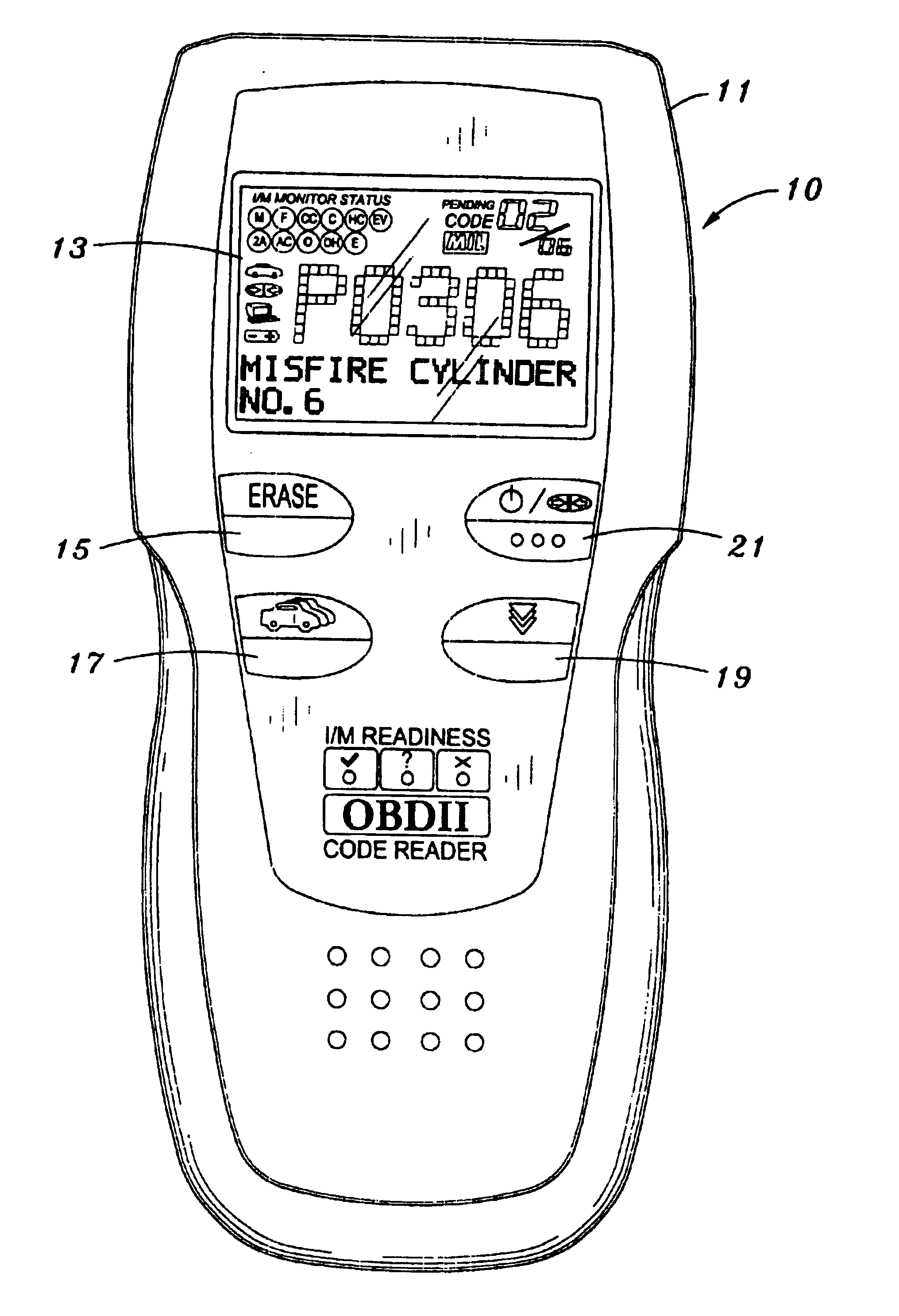
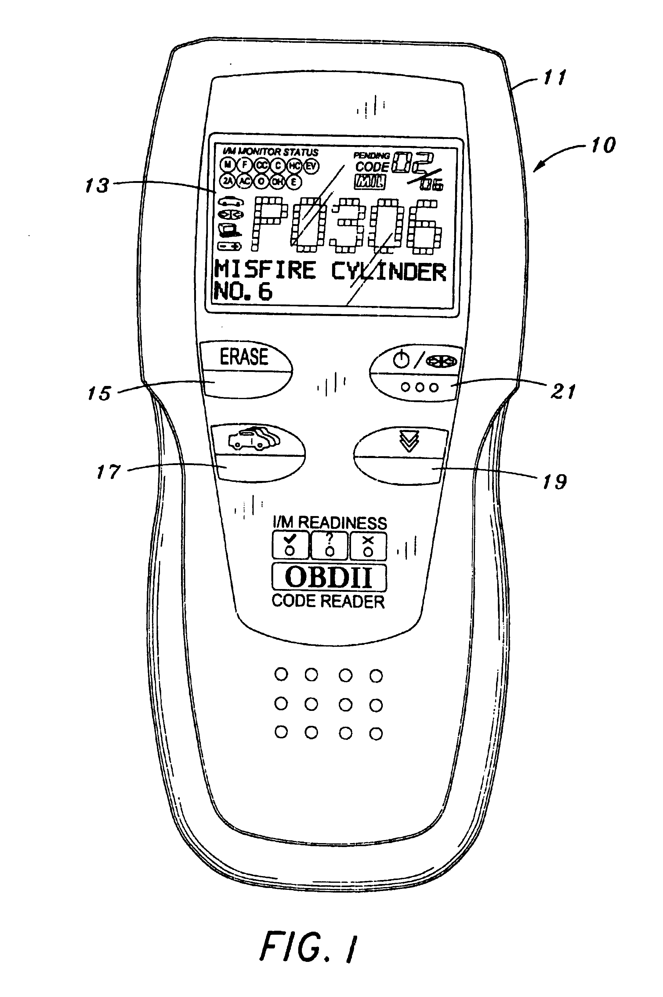
[0021]FIG. 1 illustrates a code reader 10 that operates in accordance with the present invention. The code reader 10 includes a housing 11 which incorporates active components, including electrical circuitry to implement the functions described below. The display 13 is disposed on the housing 11 and is operative to display test results, code reader functions and monitor status information as described more fully below.

[0022]Erase button 15 functions to erase diagnostic trouble codes (DTCs) and freeze frame data and resets monitor status. Scroll button 17 functions to scroll the display 13 to view diagnostic trouble codes when more than one DTC is present.

[0023]Link button 19 functions to link the code reader with the vehicle's powertrain control module (PCM) to retrieve any DTCs that are present in memory and to view readiness monitor status. Power button 21 operates to turn the code reader on and off.

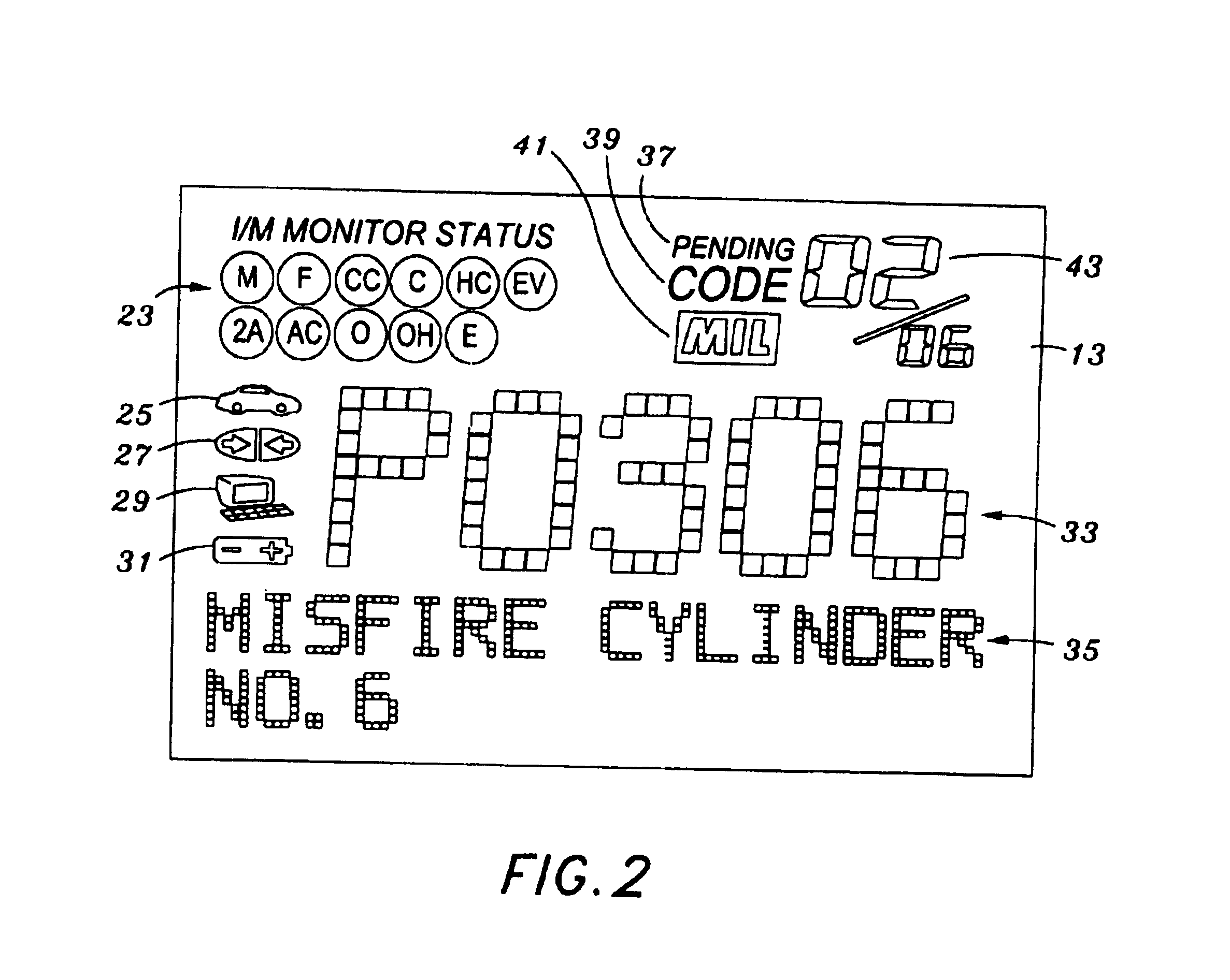
[0024]Referring to FIG. 2, the display 13 is shown in more detail. The display inc...


PUM


Abstract

A method of displaying automotive diagnostic information is disclosed comprising connecting a code reader to a vehicle computer and communicating monitor status information and trouble codes to the code reader. Only those monitor functions that are supported by the vehicle are illuminated on the code reader, along with their status. Trouble codes communicated from the vehicle are also displayed, along with trouble code descriptors. All display functions are operative independent of any manual input to identify the type of vehicle being tested.

Description

CROSS-REFERENCE TO RELATED APPLICATIONS[0001](Not Applicable)STATEMENT RE: FEDERALLY SPONSORED RESEARCH / DEVELOPMENT[0002](Not Applicable)BACKGROUND OF THE INVENTION[0003]The present invention relates generally to methods and systems for diagnosing a vehicle, and more particularly to displaying diagnostic fault codes generated by automobile computer systems.[0004]Modern motor vehicles include a computer control system. The main purpose of the vehicle computer control system is to provide maximum engine performance with the least amount of air pollution and the best fuel efficiency possible. The computer control system consists of the on-board computer and related electronic control devices (sensors, switches, and actuators). The control devices may control various systems and / or subsystems within the vehicle. These electronic control devices send information to the on-board computer about such parameters as the temperature and density of the outside air, the speed of the engine, the ...

Claims


Application Information

Patent Timeline
Patent Type & Authority Patents(United States)
IPC IPC(8): G06F19/00G07C5/00G07C5/08H01LH01L21/00
CPCG07C5/006G07C5/0825G07C2205/02G07C5/0808
Inventor ANDREASEN, KEITHCHEN, IEON C.
Owner INNOVA ELECTRONICS
Why Eureka
Try Eureka