
Combined flow, pressure and temperature sensor

a technology of pressure and temperature sensor and combined flow, which is applied in the direction of blood flow measurement, sensors, catheters, etc., can solve the problems of having to introduce two sensors into the coronary arteries, no control of the flow in the coronary arteries, etc., and achieve the effect of reliable diagnosis

Inactive Publication Date: 2007-10-02
ST JUDE MEDICAL COORDINATION CENT
View PDF19 Cites 92 Cited by
  • Summary
  • Abstract
  • Description
  • Claims
  • Application Information

AI Technical Summary

Benefits of technology

[0018]The object of the invention is therefor to make available means and methods for carrying out such combined pressure and flow measurements with a single unit, thus facilitating investigations of the outlined type, and making diagnosing more reliable.

Problems solved by technology

A limitation in measuring only the blood pressure and the pressure gradient, alternatively the Fractional Flow Reserve, is that there is no control of the flow in the coronary vessel.
It is a great drawback to have to introduce two sensors into the coronary vessel, compared to a situation where both sensors are mounted on a “guide wire”.
Thus, it has been suggested to provide a guide wire with two sensors, but this presents several technical problems with the integration of two sensors in a thin guide wire.

Method used


Image

  • Combined flow, pressure and temperature sensor
  • Combined flow, pressure and temperature sensor
  • Combined flow, pressure and temperature sensor

Examples


Embodiment Construction

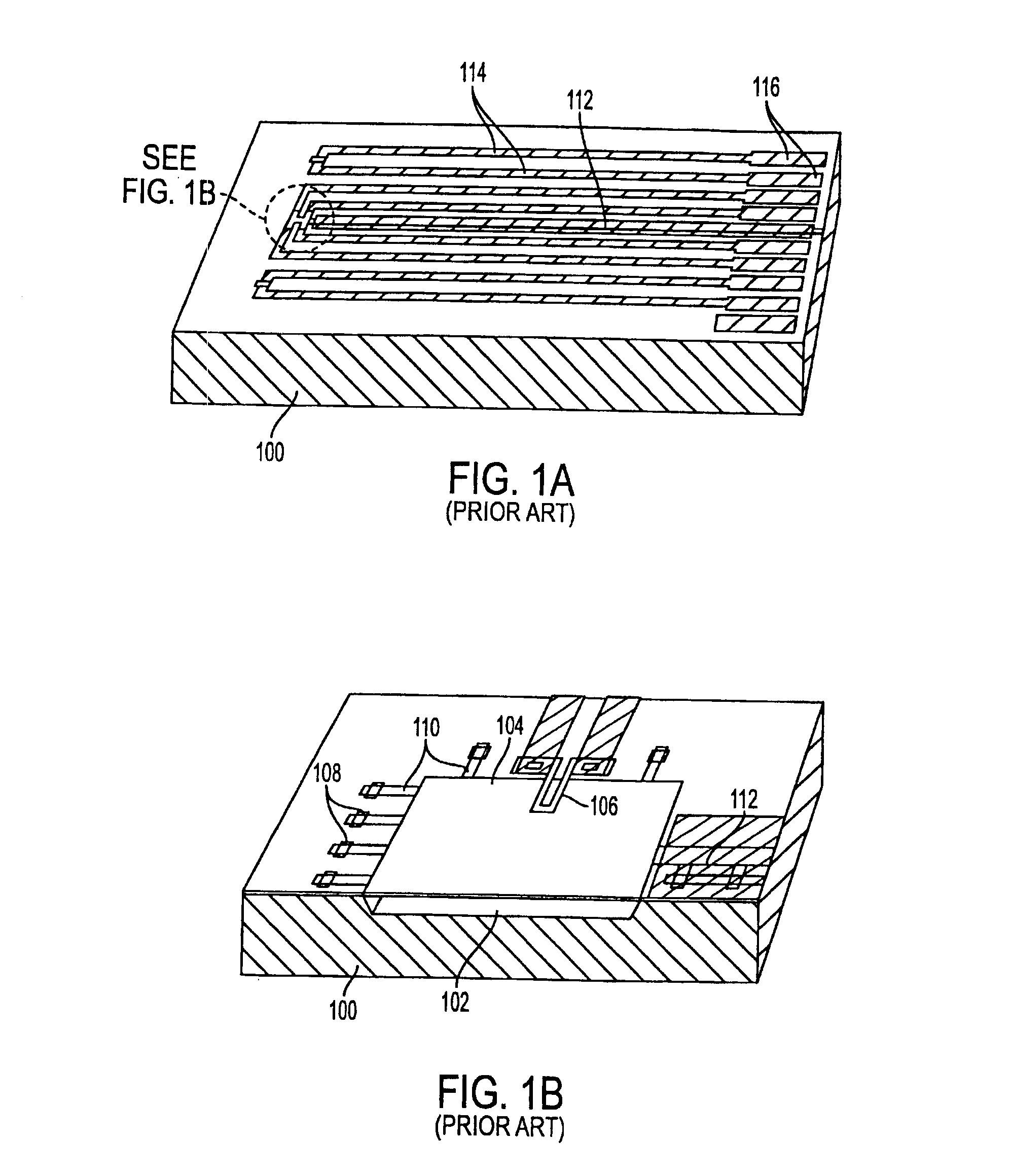
[0032]With reference to FIGS. 1a and 1b there is shown a prior art device disclosed in a publication entitled “A Small-Size Microphone for Measurements in Turbulent Gas Flows” in Sensors and Actuators A, 1994. It comprises a microphone for recording extremely small eddies in turbulent gas flows. It is based on piezoresistive techniques for transducing pressure fluctuations into electrical signals.

[0033]The microphone comprises a silicon substrate 100, and a cavity 102 in said substrate. A diaphragm of polysilicon 104 covers the cavity 102. On the diaphragm a polysilicon piezoresistor 106 is attached. Etch holes 108 and etch channels 110 are provided for manufacturing purposes. Vent channels 112 are also provided. On the substrate 100 there are metal conductors 114 and bond pads 116 for connecting cabling to external devices.

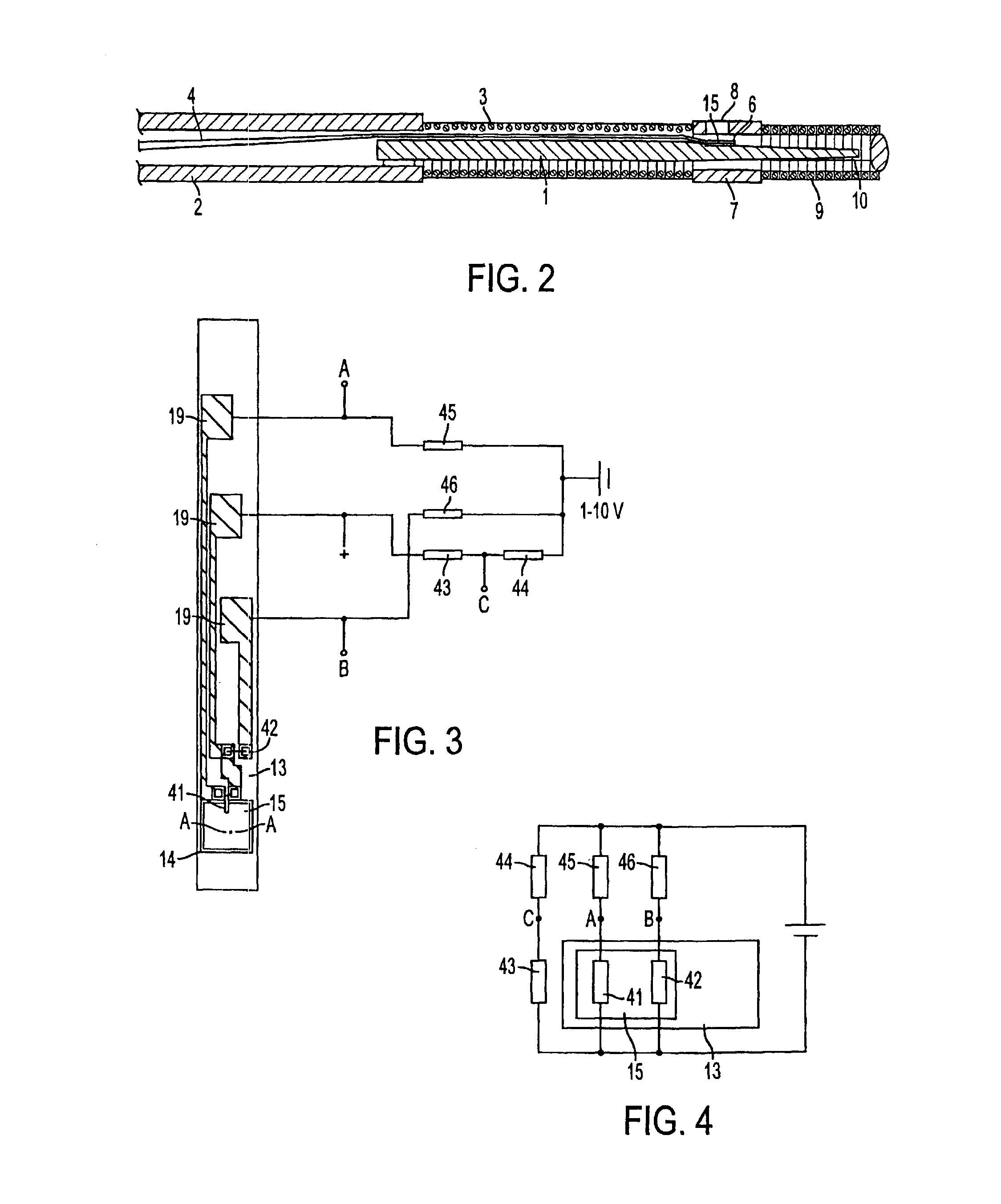
[0034]Now turning to FIG. 2 there is shown a sensor / guide device comprising a solid wire 1 which is machined by so called centering grinding, and inserted into a...


PUM


Abstract

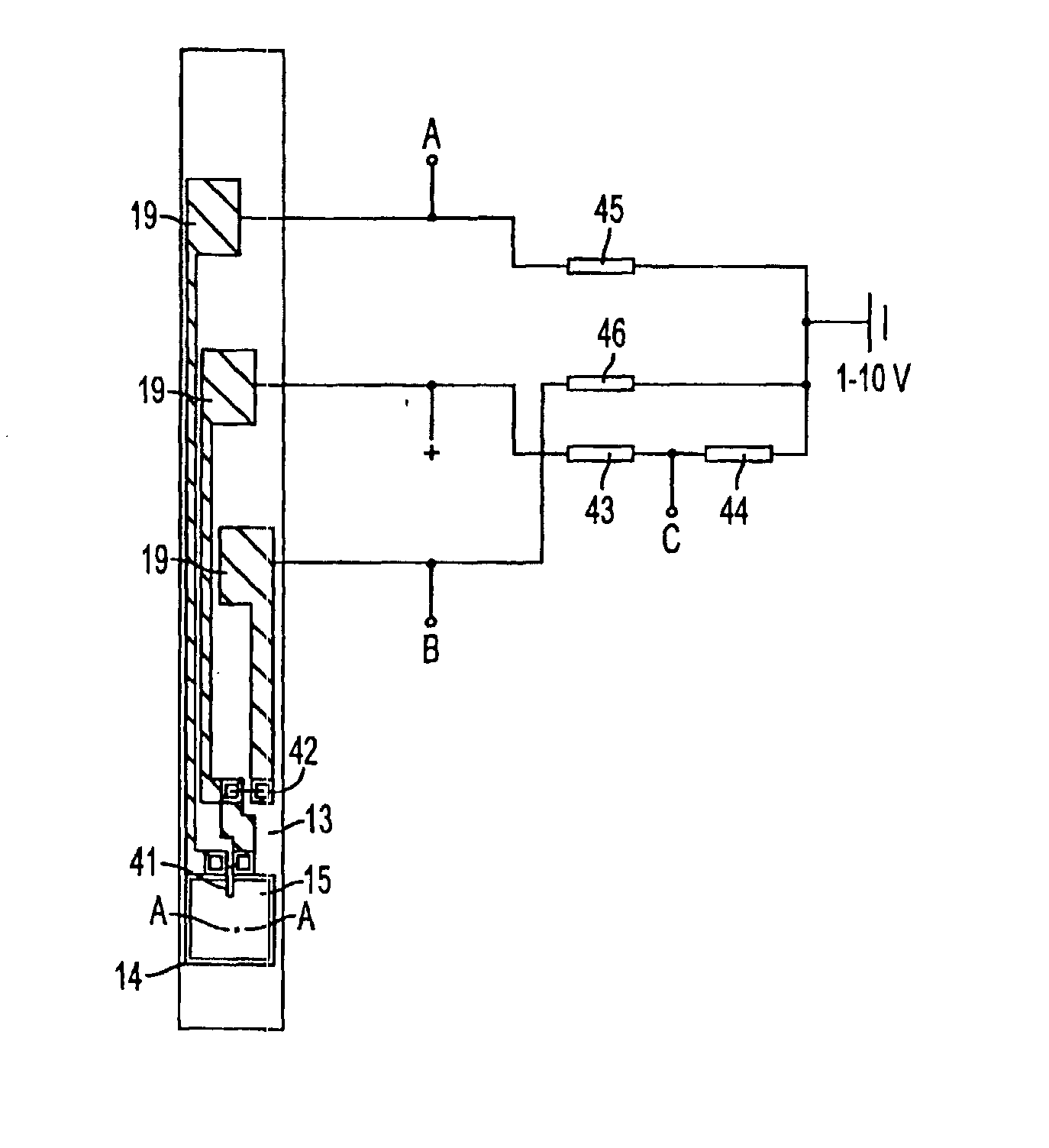
The invention relates to a device for measuring pressure, temperature and / or flow velocity. It includes a sensor (6) with a sensor support body (13) provided with a diaphragm (15) covering a cavity (14) formed in the support body (13). A pressure sensitive element (41) is mounted on the diaphragm, for recording pressure. Furthermore, a temperature sensitive resistor (42) is mounted in the vicinity of the pressure sensitive resistor and has a known temperature dependence, for recording temperature. It also includes an electrical circuit (43, 44, 45, 46) selectively outputting signals from either of the pressure sensitive element and the temperature sensitive resistor.

Description

[0001]The present invention relates generally to pressure, temperature and flow measurements, in particular in the medical field, and especially to in situ measurements of the intracoronary pressure, distally of a stricture, using a guide wire having a pressure sensor mounted at its distal end.[0002]In particular it concerns a combined flow, pressure and temperature sensor.BACKGROUND OF THE INVENTION[0003]In order to determine or assess the ability of a specific coronary vessel to supply blood to the heart muscle, i.e. the myocardium, there is known a method by which the intracoronary pressure distally of a stricture in combination with the proximal pressure is measured. The method is a determination of the so called Fractional Flow Reserve (see “Fractional Flow Reserve”, Circulation, Vol. 92, No. 11, Dec. 1, 1995, by Nico H. j. Pijls et al.). Briefly FFRmyo is defined as the ratio between the pressure distally of a stricture and the pressure proximal of a stricture, i.e. FFRmyo=Pdi...

Claims


Application Information

Patent Timeline
IPC IPC(8): G01L9/02G01L19/04A61B5/0205A61B5/01A61B5/0215A61B5/028A61B5/0295A61M25/00A61M25/01G01F1/684G01K1/04G01L9/00G01L19/00
CPCA61B5/0215A61B5/028A61M2025/0002G01F1/6845G01K1/045G01L19/0092G01L19/148
Inventor SMITH, LEIF
Owner ST JUDE MEDICAL COORDINATION CENT
Learn More