Percutaneous registration apparatus and method for use in computer-assisted surgical navigation
What is Al technical title?
Al technical title is built by PatSnap Al team. It summarizes the technical point description of the patent document.
a registration apparatus and surgical navigation technology, applied in the direction of diagnostic recording/measuring, application, osteosynthesis devices, etc., can solve the problems of irritating the patient, trauma, blood loss, post-operative pain,
Inactive Publication Date: 2011-03-01
MEDTRONIC NAVIGATION INC
View PDF634 Cites 141 Cited by
Summary
Abstract
Description
Claims
Application Information
AI Technical Summary
This helps you quickly interpret patents by identifying the three key elements:
Problems solved by technology
Method used
Benefits of technology
[0018]It is a further object of this invention to provide a system and method to simply and yet positively indicate to the user a change in position of body parts, such as spinal vertebrae segments, from that identified in a stored image scan, such as from an MRI or CAT scan, and provide a method to realign those body parts to correspond with a previously stored image or the image to correspond with the actual current position of the body parts.
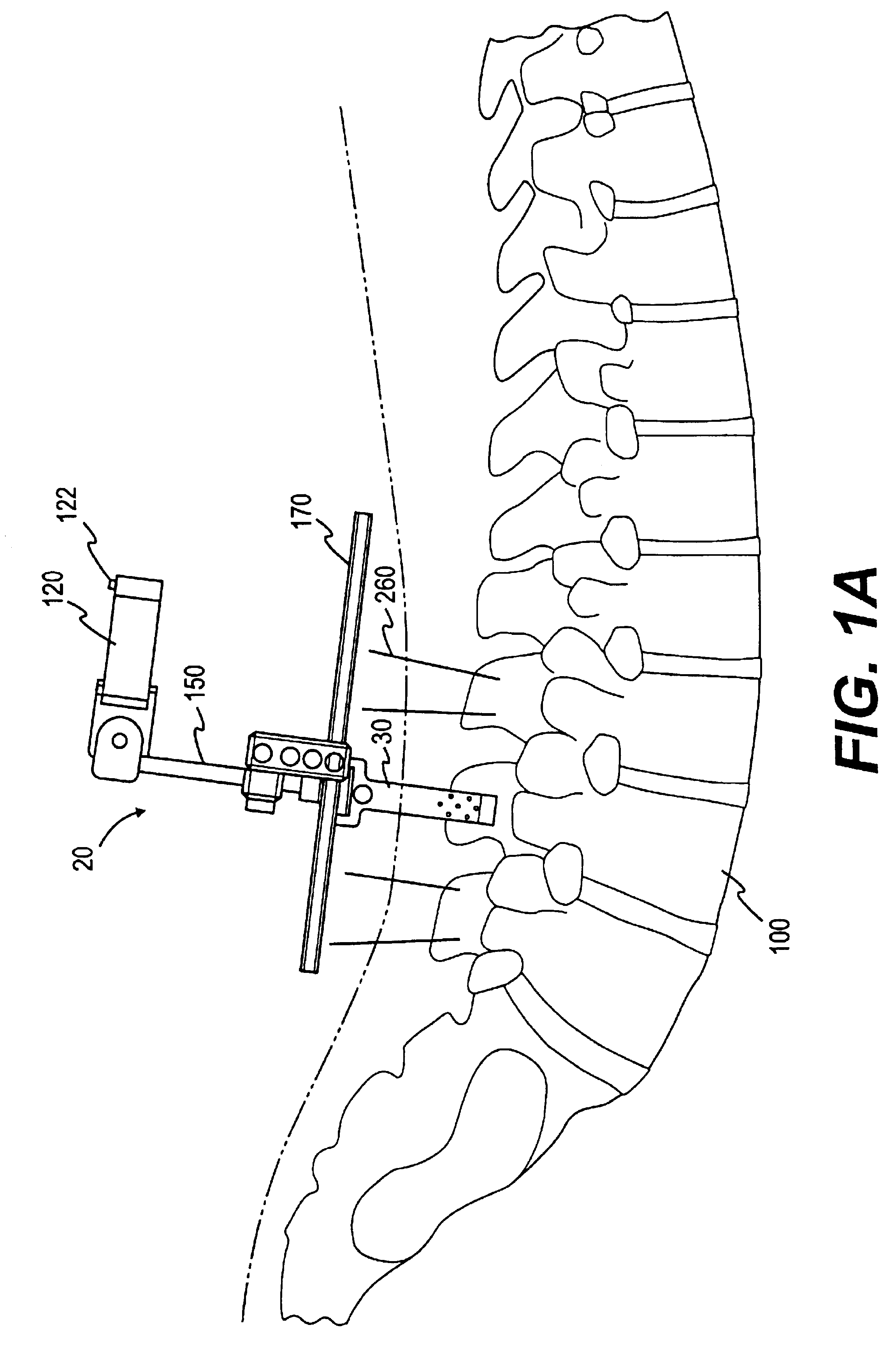
[0020]It is another object of this invention to provide a system and method for positively generating a display of instruments and surgical implants, such as, for example screws and rods, placed percutaneously in a patient using image-guided surgical methods and techniques.
Problems solved by technology
This standard procedure is invasive and can result in trauma, blood loss, and post operative pain.
However, this technique can be difficult in that fluoroscopes only provide two-dimensional images and require the surgeon to rotate the fluoroscope frequently in order to get a mental image of the anatomy in three dimensions.
Additionally, the subcutaneous implants required for this procedure may irritate the patient.
This is due in part to the fact that there is no fluoroscopic technique that has been designed which can always adequately place rods or plates at the submuscular region (or adjacent to the vertebrae).
These subcutaneous rods or plates may not be well tolerated by the patient.
They also may not provide the optimal mechanical support to the spine because the moment arm of the construct can be increased, thereby translating higher loads and stresses through the construct.
When there is an opportunity for anatomical movement, such movement degrades the fidelity of the pre-procedural images in depicting the intra-procedural anatomy.
Furthermore, spinal surgical procedures are typically highly invasive.
Method used
Image
Click on the blue label to locate the original text in one second.
Reading with bidirectional positioning of images and text.
Examples
Embodiment Construction
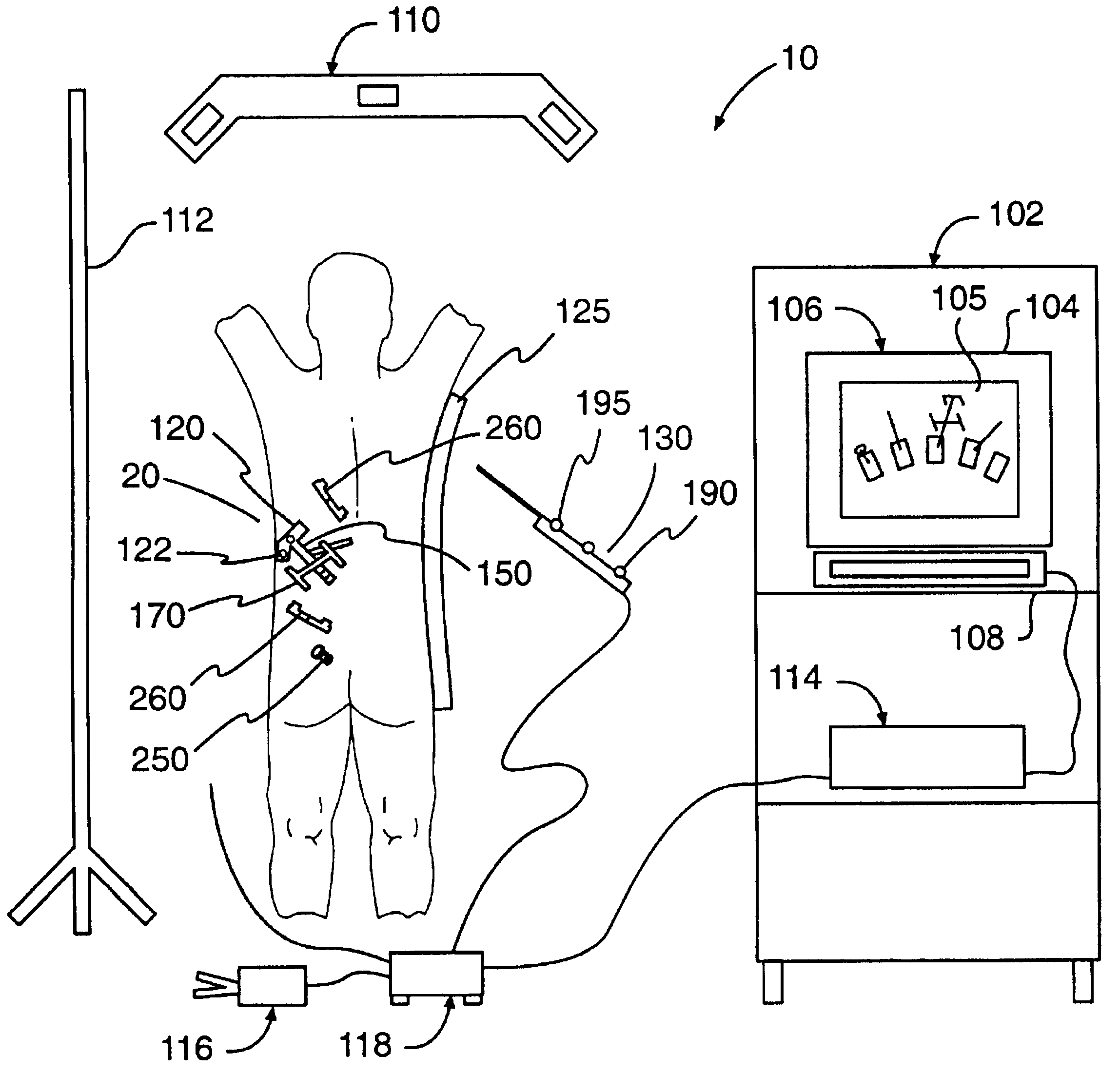
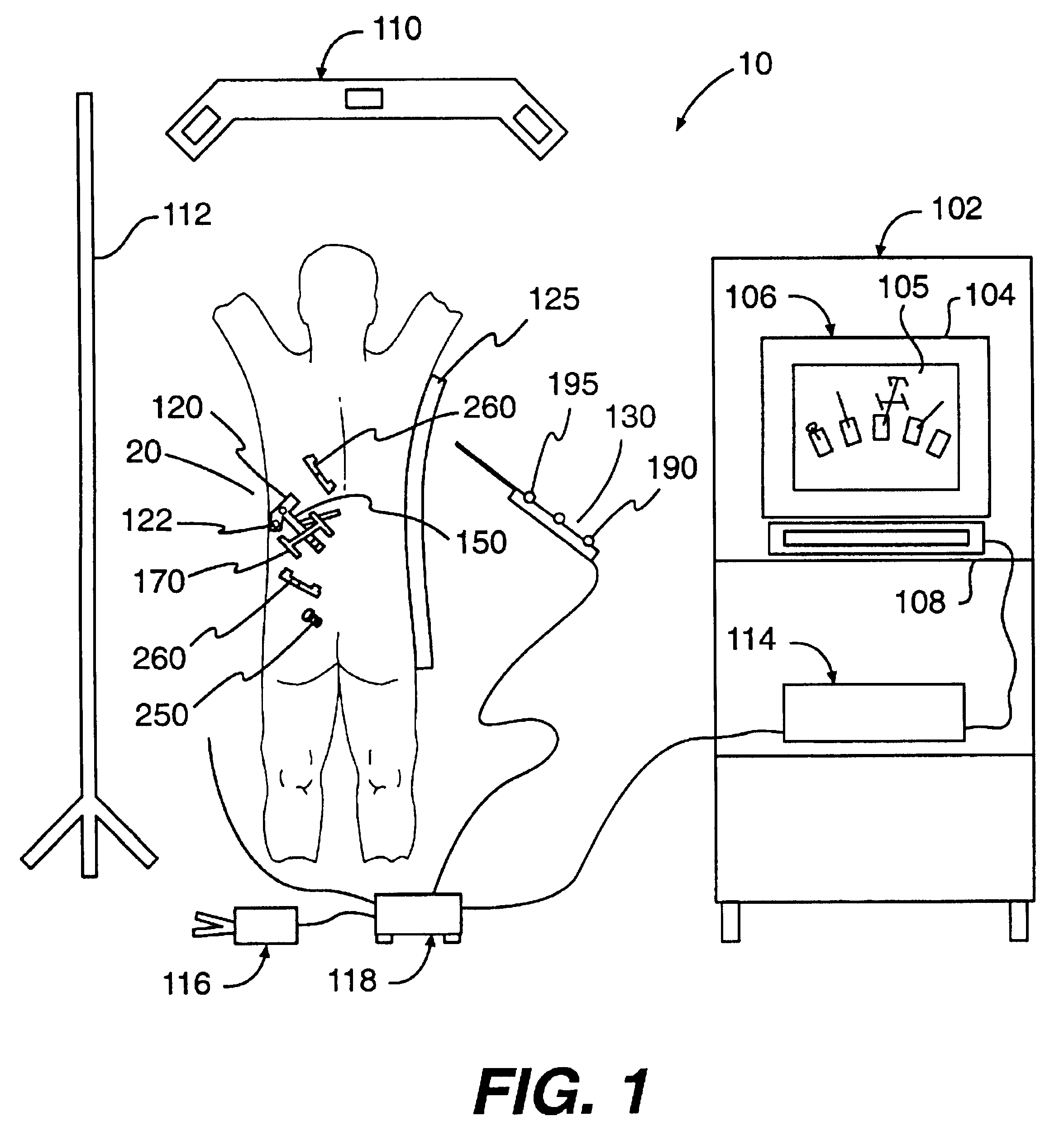
[0053]Reference will now be made in detail to the present preferred embodiment of the invention, an example of which is illustrated in the accompanying drawings. Wherever possible, the same reference numbers will be used throughout the drawings to refer to the same or like parts. The following example is intended to be purely exemplary of the invention.
[0054]As generally described in PCT / US95 / 12894, the entire disclosure of which is incorporated herein by reference, a typical surgical navigation system is shown in FIG. 1 adopted to be used in the present invention. A computer assisted image-guided surgery system, indicated generally at 10, generates an image for display on a monitor 106 representing the position of one or more body elements, such as spinal elements fixedly held in a stabilizing frame or device such as a spinal surgery frame 125 commonly used for spinal surgery. A reference arc 120 bearing tracking means or emitters, such as for example LED emitters 122, is mounted t...
PUM
Abstract
An apparatus and procedures for percutaneous placement of surgical implants and instruments such as, for example, screws, rods, wires and plates into various body parts using image guided surgery. The invention includes an apparatus for use with a surgical navigation system, an attaching device rigidly connected to a body part, such as the spinous process of a vertebrae, with an identification superstructure rigidly but removably connected to the attaching device. This identification superstructure, for example, is a reference arc and fiducial array which accomplishes the function of identifying the location of the superstructure, and, therefore, the body part to which it is fixed, during imaging by CAT scan or MRI, and later during medical procedures.
Description
[0001]This application is a reissue of U.S. Pat. No. 6,226,548 issued on May 1, 2001 and also claims benefit under 35 U.S.C. §120 as a continuation of U.S. patent application Ser. No. 10 / 423,332 filed on Apr. 24, 2003, now RE 39,133; which is a reissue of U.S. Pat. No. 6,226,548 issued on May 1, 2001; which claims rights under 35 U.S.C. §119 on provisional application No. 60 / 059,915, filed on Sep. 24, 1997. Notice is also given that concurrently filed is U.S. patent application Ser. No. 09 / 148,498 filed on Sep. 4, 1998; which is also is a reissue of U.S. Pat. No. 6,226,548 issued on May 1, 2001 and also claims benefit under 35 U.S.C. §120 as a continuation of U.S. patent application Ser. No. 10 / 423,332 filed on Apr. 24, 2003; which is a reissue of U.S. Pat. No. 6,226,548 issued on May 1, 2001; which claims rights under 35 U.S.C. §119 on provisional application No. 60 / 059,915, filed on Sep. 24, 1997. The disclosures of the above applications are incorporated herein by reference.[0002...
Claims
Application Information
Patent Timeline
Application Date:The date an application was filed.
Publication Date:The date a patent or application was officially published.
First Publication Date:The earliest publication date of a patent with the same application number.
Issue Date:Publication date of the patent grant document.
PCT Entry Date:The Entry date of PCT National Phase.
Estimated Expiry Date:The statutory expiry date of a patent right according to the Patent Law, and it is the longest term of protection that the patent right can achieve without the termination of the patent right due to other reasons(Term extension factor has been taken into account ).
Invalid Date:Actual expiry date is based on effective date or publication date of legal transaction data of invalid patent.