Electrical clamp connector and connecting terminal

a technology of connecting terminals and clamp connectors, which is applied in the direction of coupling device connections, contact member penetrating/cutting insulation/cable strands, contact member manufacturing, etc., can solve the problems of large space occupation of known terminals of this type, and achieve the effect of cost-effectiveness

Active Publication Date: 2013-09-10
WAGO VERW GMBH
View PDF8 Cites 16 Cited by
  • Summary
  • Abstract
  • Description
  • Claims
  • Application Information

AI Technical Summary

Benefits of technology

This patent describes a solution for creating a small-sized terminal from a single piece of spring steel sheet and a busbar rod. The busbar rod has cross projections that form additional connecting contacts with the spring steel sheet. The cross projections can be positioned on either side of the spring steel sheet, forming a socket or plug-in contact. The busbar rod has a V-shaped or U-shaped cross-sectional form and lies against the spring steel sheet, with its margin edges running in the lengthwise direction of the rod. The cross projections can be produced in one piece with the busbar rod or separately and joined as a finished assembly. The technical effect of this solution is a highly cost-effective and efficient way to create small-sized terminals when compared to previous designs.

Problems solved by technology

However, a drawback is that the known terminals of this type require a lot of space.

Method used


Image

  • Electrical clamp connector and connecting terminal
  • Electrical clamp connector and connecting terminal
  • Electrical clamp connector and connecting terminal

Examples


Embodiment Construction

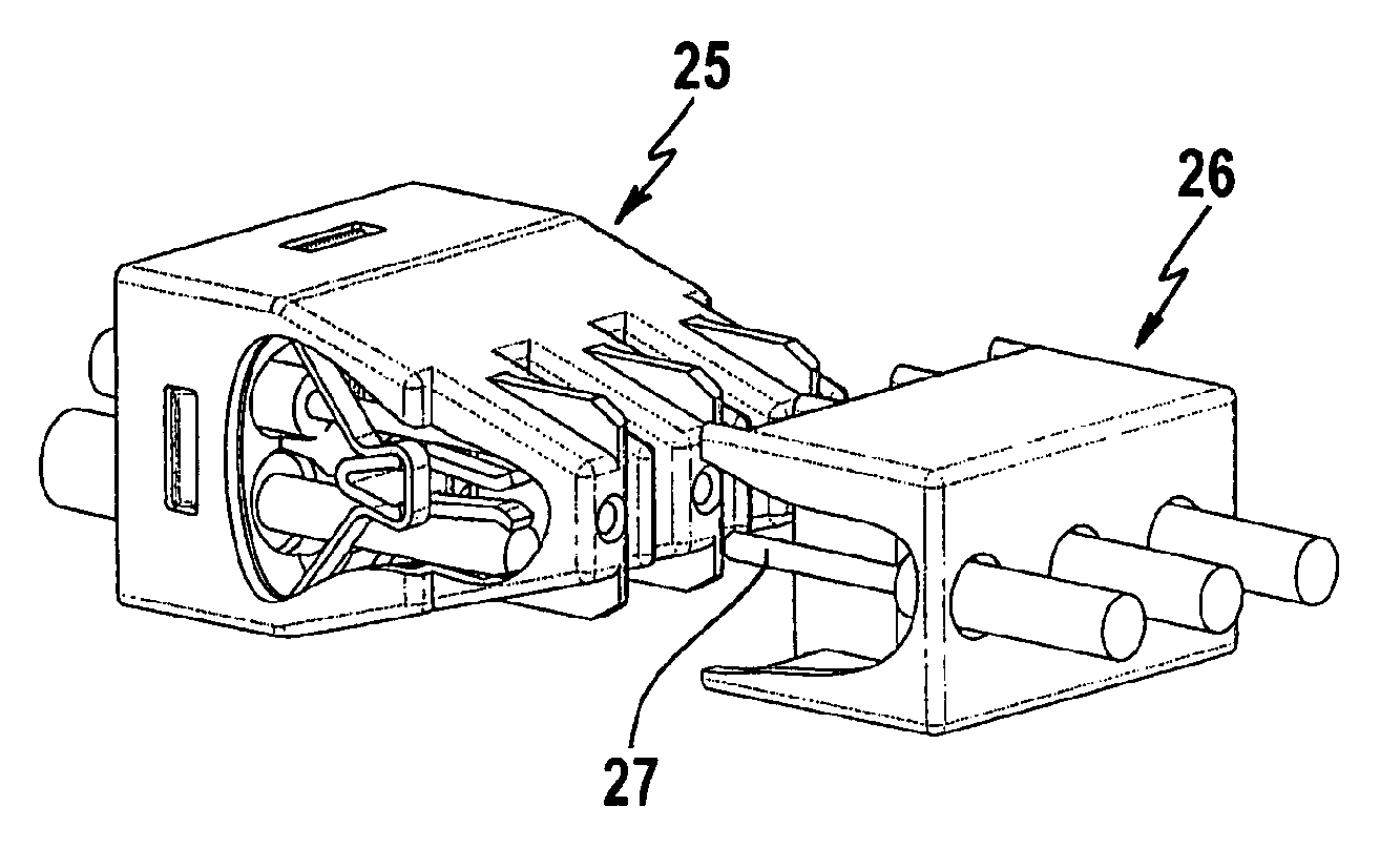
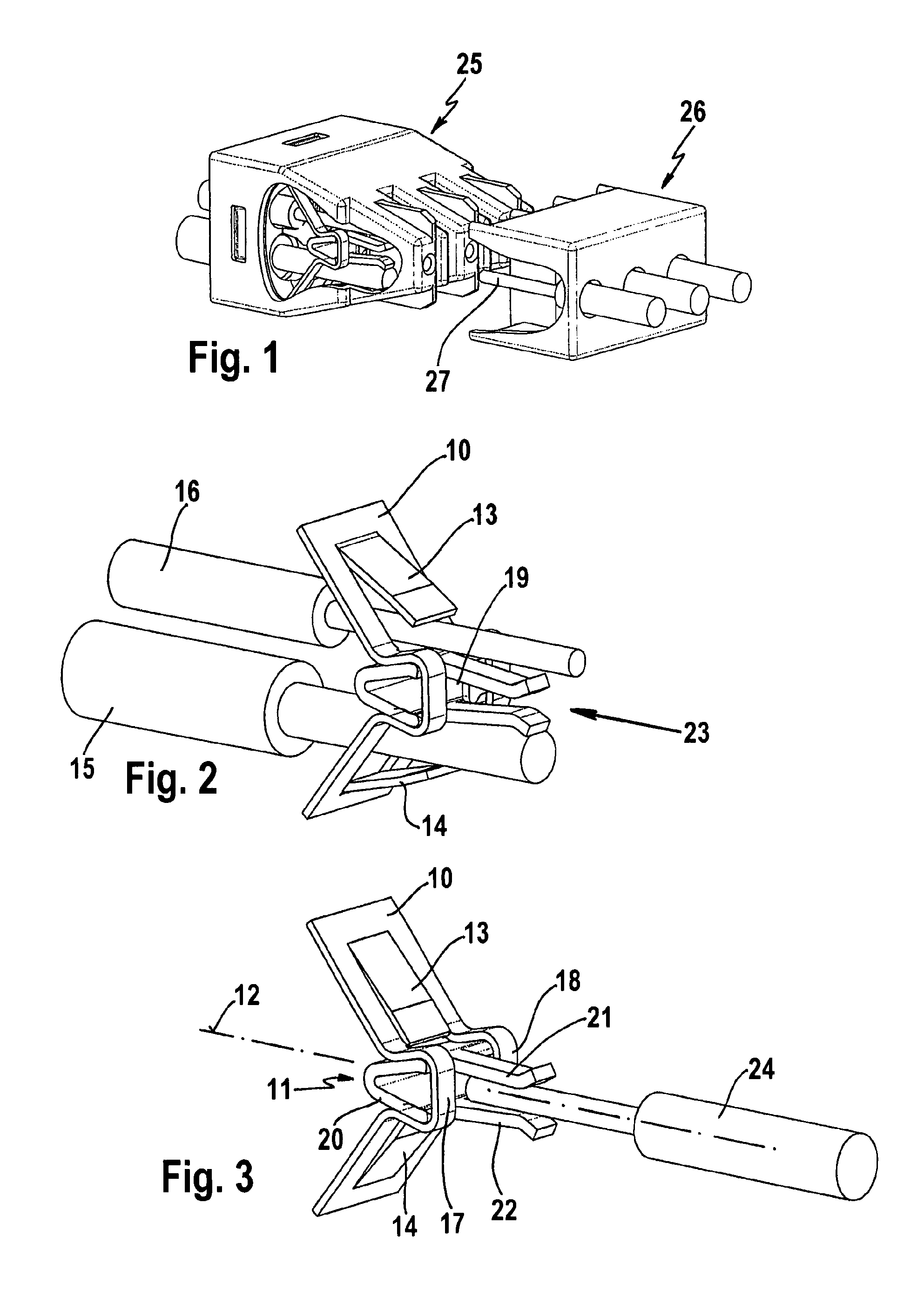
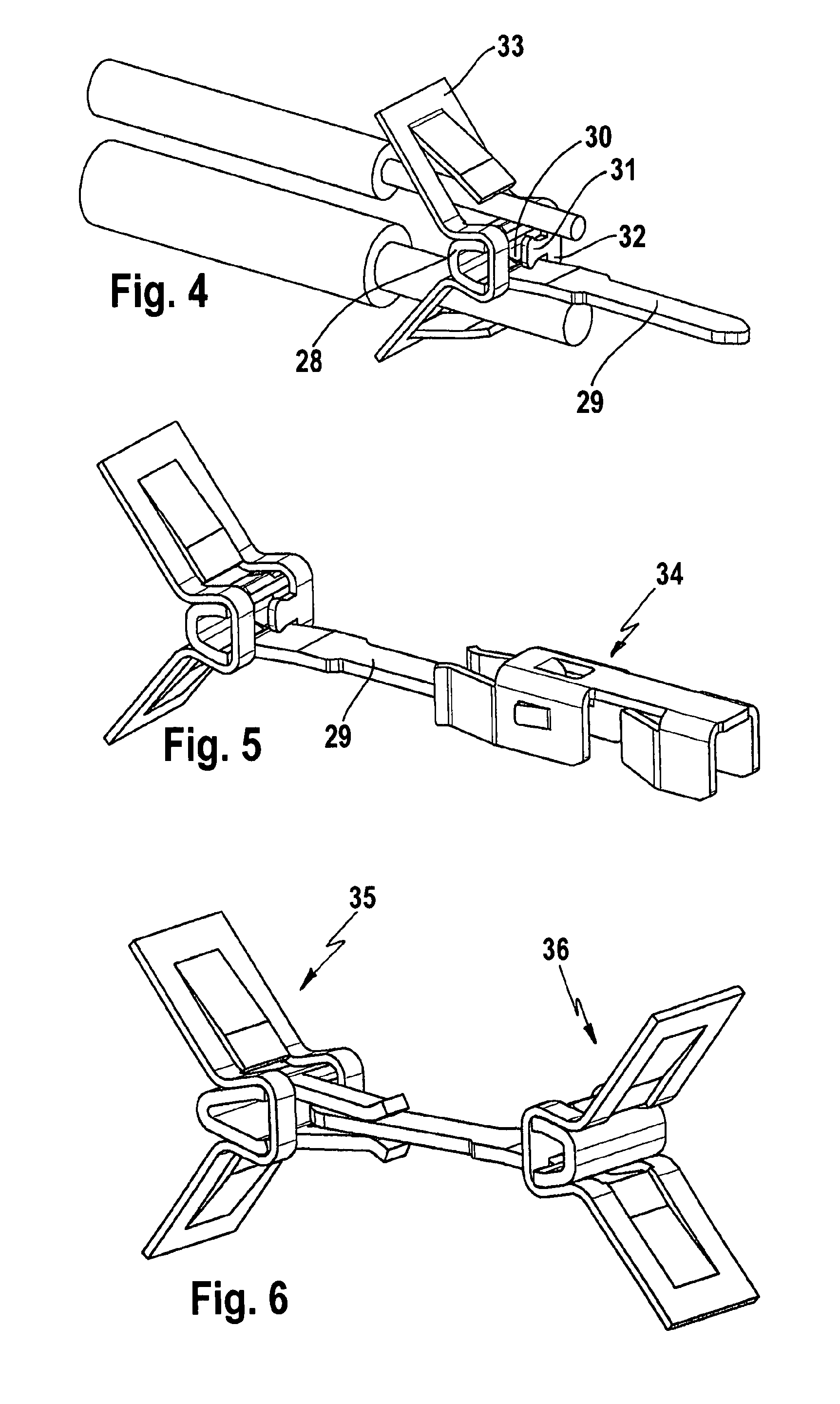
[0014]FIGS. 2 and 3 show a one-pole clamp connector and connecting terminal, consisting of one piece of spring steel sheet 10 and a busbar rod 11.

[0015]From the piece of spring steel sheet 10, a pair of leaf springs 13, 14 are cut out mirror-symmetrically to the central plane 12 (see FIG. 3) and, together with the busbar rod 11, each forms a terminal site for connecting the electrical conductors 15 and 16. The electrical conductors may have different conductor cross sections, because the cut-out leaf spring tongues 13 and 14 work independently of each other and are joined together only via the two outer crosspieces 17 and 18 (see FIG. 3) of the spring steel sheet. The crosspieces 17 and 18, in turn, are locked together with the busbar rod 11 in fixed position.

[0016]The busbar rod 11 is constructed with a V shape in cross section and has a spine 20 (in the embodiment example depicted, this is the V-shaped bent part of the busbar rod) and two cross projections 21 and 22 projecting awa...


PUM


Abstract

The invention relates to an electrical clamp connector and connecting terminal that, per pole, has at least two conductor terminal connections oriented in the same direction and an additional connecting contact on the opposite-lying side, which serves for connecting a countercontact external to the terminal. It is proposed for such a terminal to use the especially small-construction design features of a terminal that is produced from a single piece of spring steel sheet and a busbar rod, and to combine these with the new features that the busbar rod has one or two cross projections, which project through the free opening in the spring steel sheet and form the additional connecting contact, which, for example, may be constructed in the form of a socket contact or in the form of a plug-in contact.

Description

BACKGROUND OF THE INVENTION[0001]The invention relates to an electrical clamp connector and connecting terminal that, per pole, has at least two spring clamp connectors, which are opposite-lying and mirror-symmetric with respect to a central plane, for connecting electrical conductors, in which the electrical conductors can be plugged in from the same connection direction and by means of which the electrical conductors can be connected electrically to a common busbar in the interior of the terminal, the busbar having an additional connecting contact, which is arranged in the central plane between the two conductor clamp connections on the side of the terminal facing away from the conductor clamp connections and serves for connecting a countercontact external to the terminal.[0002]Electrical clamp connectors and connecting terminals of this type are known (see DE 94 20 097 U1). They are produced with one pole or multiple poles; for example, in a multi-pole embodiment, several one-pol...

Claims


Application Information

Patent Timeline
Patent Type & Authority Patents(United States)
IPC IPC(8): H01R4/48
CPCH01R9/2491H01R13/055H01R13/111H01R13/113H01R13/502H01R43/16H01R13/025H01R4/48185
Inventor KIRSTEIN, AXELSTROMIEDEL, KONRAD
Owner WAGO VERW GMBH
Why Eureka
Try Eureka