Small size automatic two-wheel cycle

An automatic two-wheeler, small technology, applied in the direction of motor vehicles, bicycles, bicycle accessories, etc., can solve the problems of increased manufacturing cost of leg guards, cable disconnection, etc., to prevent cable disconnection, reduce the number, and fix the structure simple effect

Inactive Publication Date: 2007-09-12
YAMAHA MOTOR CO LTD
View PDF8 Cites 0 Cited by
  • Summary
  • Abstract
  • Description
  • Claims
  • Application Information

AI Technical Summary

Problems solved by technology

Also, the connector can move around while driving, potentially disconnecting the cable
[0006] When eliminating this disadvantage, there should be no unnecessary increase in the manufacturing cost of the shin guards

Method used


Image

  • Small size automatic two-wheel cycle
  • Small size automatic two-wheel cycle
  • Small size automatic two-wheel cycle

Examples


Embodiment Construction

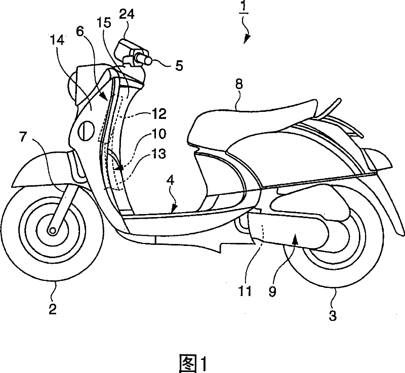
[0027] An embodiment of the small automatic two-wheeled vehicle of the present invention will be described in detail below by means of Fig. 1 to Fig. 13 .

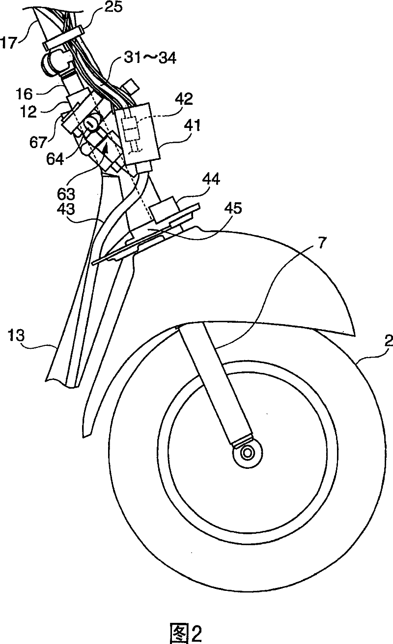
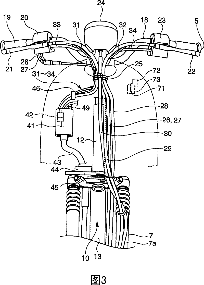
[0028] Fig. 1 is a side view of a small automatic two-wheel vehicle in the present invention; Fig. 2 is a side view of the car body front after the leg guard is removed; Fig. 3 is its front view; Fig. 4 is a rear view of the rear panel of the leg guard ; FIG. 5 is a diagram showing a cup for holding cables, in which (a) is a front view and (b) is a side view. Fig. 6 is a bottom view of the cup for holding cables; Fig. 7 is a cross-sectional view of line VII-VII in Fig. 6; Fig. 8 is a cross-sectional view of line VIII-VIII in Fig. 6 . Fig. 9 is a cross-sectional view along line IX-IX of the rear panel in Fig. 4 . Fig. 10 is a side view of a bracket for mounting a cup, wherein (a) is a front view, and (b) is a side view. Fig. 11 is a view showing a clip, in which (a) is a cross-sectional view, (b) is a front view, and (c) ...


PUM


Abstract

The purpose of this inventio is to hinder noise emission by holding certainly a connector installed inside a leg shield. A cup 41 formed from rubber into a bottom-equipped cylinder and furnished with a hole for threading of cables at the bottom is provided inside the leg shield 6. A plurality of cables are threaded into the cup 41. The connector 42 of the cables is accommodated in the cup 41. The cup 41 is fixed to a bracket 50 on a back face plate 15.

Description

technical field [0001] The present invention relates to a small-sized automatic two-wheeled vehicle in which a plurality of cables are arranged inside a leg shield. Background technique [0002] Conventionally, as a small motorcycle in which a plurality of cables are routed in the leg cover, a member for holding the cable in the leg cover is provided so that the cable is held at a predetermined position in the leg cover. For example, Patent Document 1 discloses such a conventional small-sized motorcycle. [0003] The small automatic two-wheel vehicle shown in this patent document 1 (Japanese Patent Laying-Open No. 2000-62675, pages 2-3, Fig. 4) is provided with a leg guard below the steering handle, and the inside of the leg guard is clothed with Multiple cables connected to various switches. These cables are inserted into and pass through retaining grooves formed in the leg shield, thereby being held at predetermined positions within the leg shield. The groove is formed ...

Claims


Application Information

Patent Timeline
IPC IPC(8): B62K11/00B62J17/06B62J39/00B62J11/19B62J99/00
Inventor 铃木诚之
Owner YAMAHA MOTOR CO LTD
Why Eureka
Try Eureka