Control method of complex heat pump

A control method and heat pump technology, applied in domestic heating, heating and ventilation control systems, applications, etc., can solve problems such as overheating of compressor 22, reduction of heating performance, and increase of temperature on the outlet side of the compressor

Inactive Publication Date: 2007-09-19
LG ELECTRONICS INC
View PDF5 Cites 0 Cited by
  • Summary
  • Abstract
  • Description
  • Claims
  • Application Information

AI Technical Summary

Problems solved by technology

This fact means that the amount of refrigerant circulated to the compressor 22 is reduced, causing the cooling efficiency to decrease and the compressor 22 to overheat
Such overheating of the compressor 22 increases the temperature on the outlet side of the compressor, resulting in reduced heating performance, while damaging and shortening the life of the compressor 22

Method used


Image

  • Control method of complex heat pump
  • Control method of complex heat pump
  • Control method of complex heat pump

Examples


Embodiment Construction

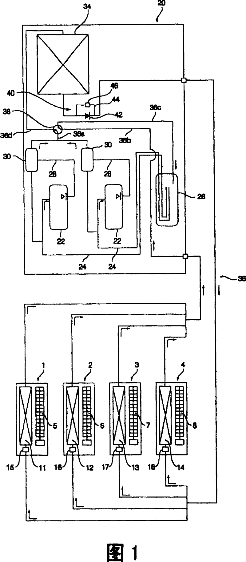
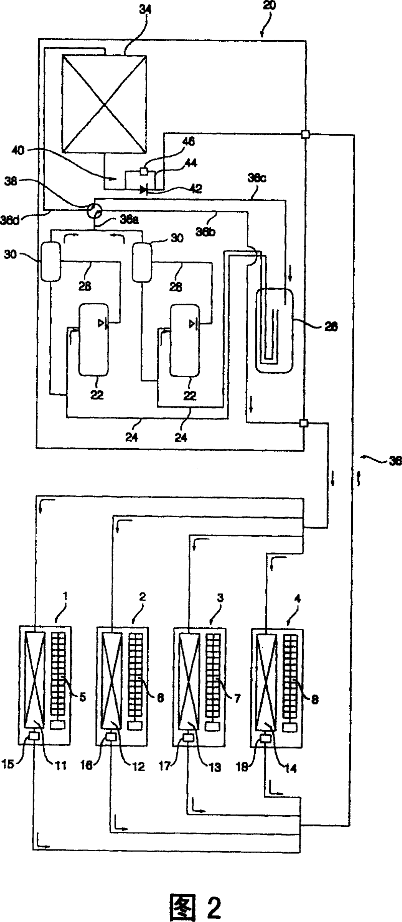
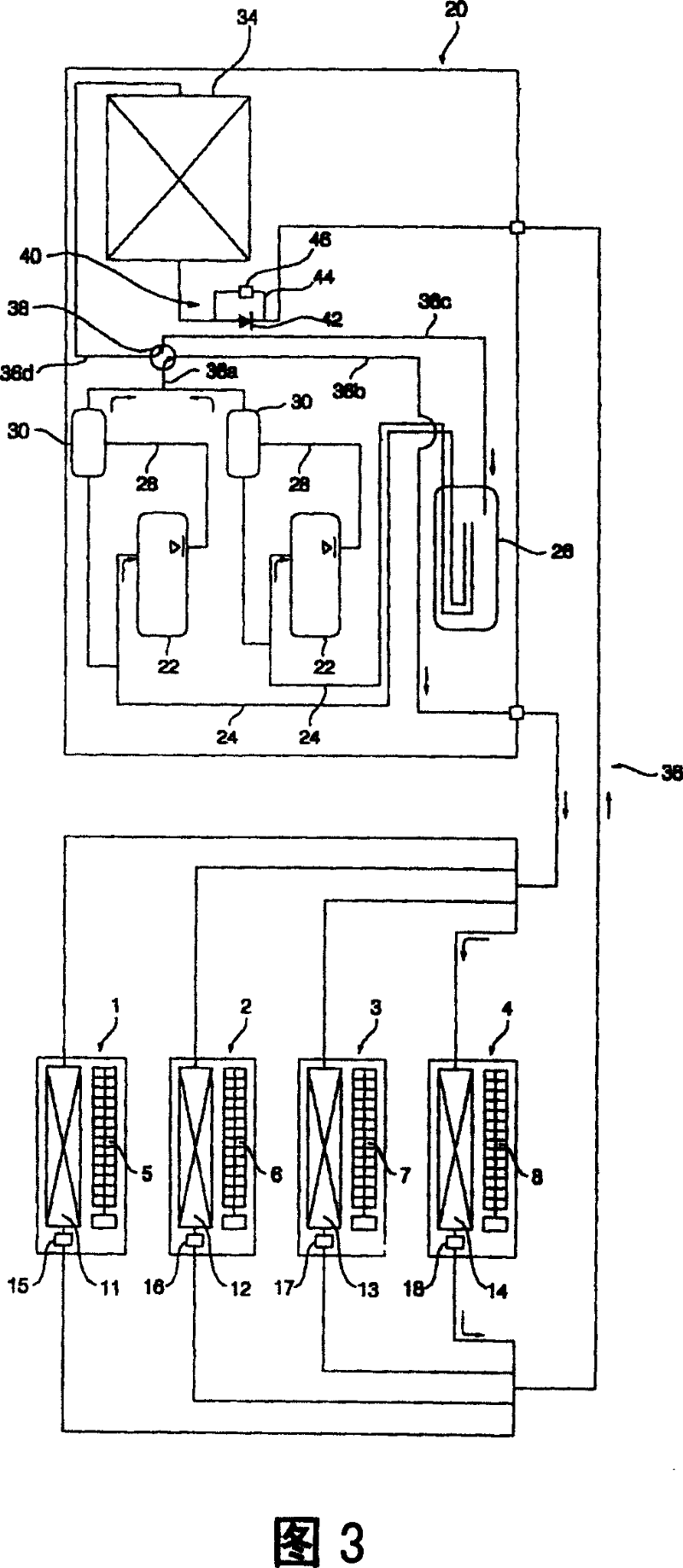
[0052] A preferred embodiment of a control method for a compound heat pump according to the present invention will be described in detail below with reference to FIGS. 4 to 8 . Hereinafter, the constituent elements of the compound heat pump according to the present invention respectively corresponding to the above-mentioned conventional compound heat pump constituent elements are denoted by the same reference numerals, and no detailed description will be given.

[0053] Fig. 4 shows a schematic diagram of the cycle of refrigerant flow in the compound heat pump according to the present invention when one indoor unit is operating in a heating mode and the other indoor units are not operating.

[0054] As shown in FIG. 4 , the complex heat pump according to the present invention includes a plurality of indoor units 1 , 2 , 3 and 4 and a single outdoor unit 20 .

[0055] Each of the indoor units 1, 2, 3 or 4 is provided with: an indoor blower 5, 6, 7 or 8, which sucks in indoor ai...


PUM


Abstract

Disclosed herein is a control method for a multiple heat pump. In the control method, when one of multiple indoor units operates in the heating mode and the other indoor units shut down, electronic expansion valves of the shutdown indoor units are controlled to have an opening degree higher than a standard opening degree if an outlet temperature of compressors is higher than a preset temperature, so as to permit a liquid refrigerant, remaining in the shutdown indoor units, to be more readily recovered to the compressors. This eliminates a refrigerant shortage phenomenon of the compressors and prevents deterioration of heating performance as well as reduction of life-span of the compressors.

Description

technical field [0001] The present invention relates to a multiple heat pump, and more particularly to a control method of the multiple heat pump, which can make the heat pump remaining in the stopped operation when only one of the multiple indoor units operates in the heating mode. Liquid refrigerant in the indoor unit returns to the compressor. Background technique [0002] Fig. 1 shows a schematic diagram of the cycle of refrigerant flow in the cooling mode of a conventional compound heat pump. Fig. 2 shows a schematic diagram of the cycle of refrigerant flow in the heating mode of a conventional compound heat pump. Fig. 3 shows a schematic diagram of the cycle of refrigerant flow when one indoor unit among the indoor units of a conventional compound heat pump operates in a heating mode and the other indoor units stop operating. [0003] As shown in FIGS. 1 to 3 , a conventional complex heat pump includes a plurality of indoor units 1 , 2 , 3 and 4 . Each indoor unit 1...

Claims


Application Information

Patent Timeline
Patent Type & Authority Patents(China)
IPC IPC(8): F25B13/00F24F11/00F25B49/02F25B5/02
CPCY02B30/72
Inventor 黄一男吴世基李相虎张世东李润彬
Owner LG ELECTRONICS INC
Why Eureka
Try Eureka