

Liquid crystal display apparatus
a technology of liquid crystal display and display device, which is applied in the direction of instruments, optical light guides, optics, etc., can solve the problems of low-temperature fluorescent tubes, mercury in cold cathode fluorescent tubes etc., and the life of light-emitting diodes described above is likely to be short, so as to prevent the reduction of the life of light-emitting diodes resulting from a temperature increase with certainty
- Summary
- Abstract
- Description
- Claims
- Application Information
AI Technical Summary
Benefits of technology
Problems solved by technology
Method used
Image

Examples
embodiment 1
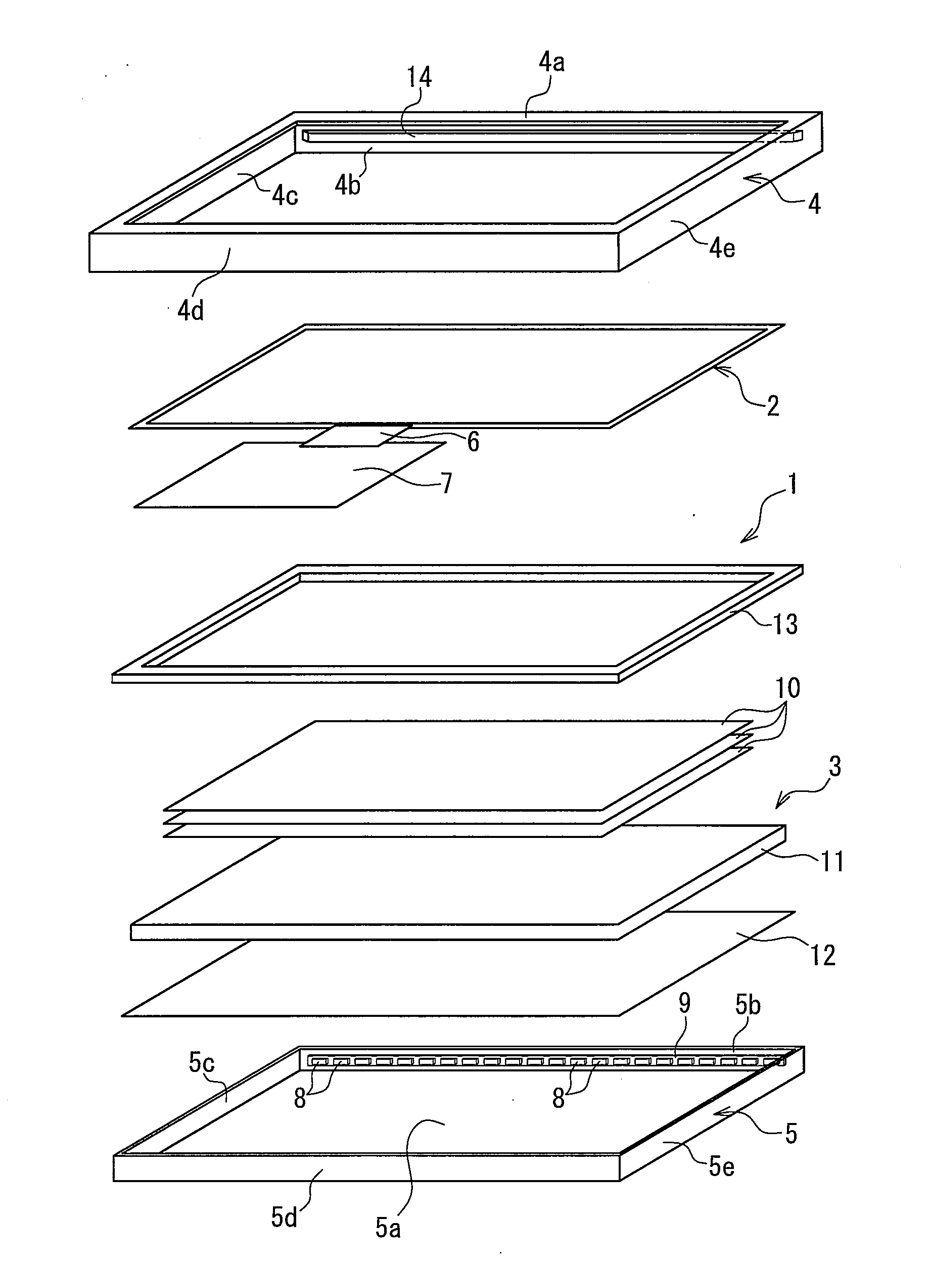
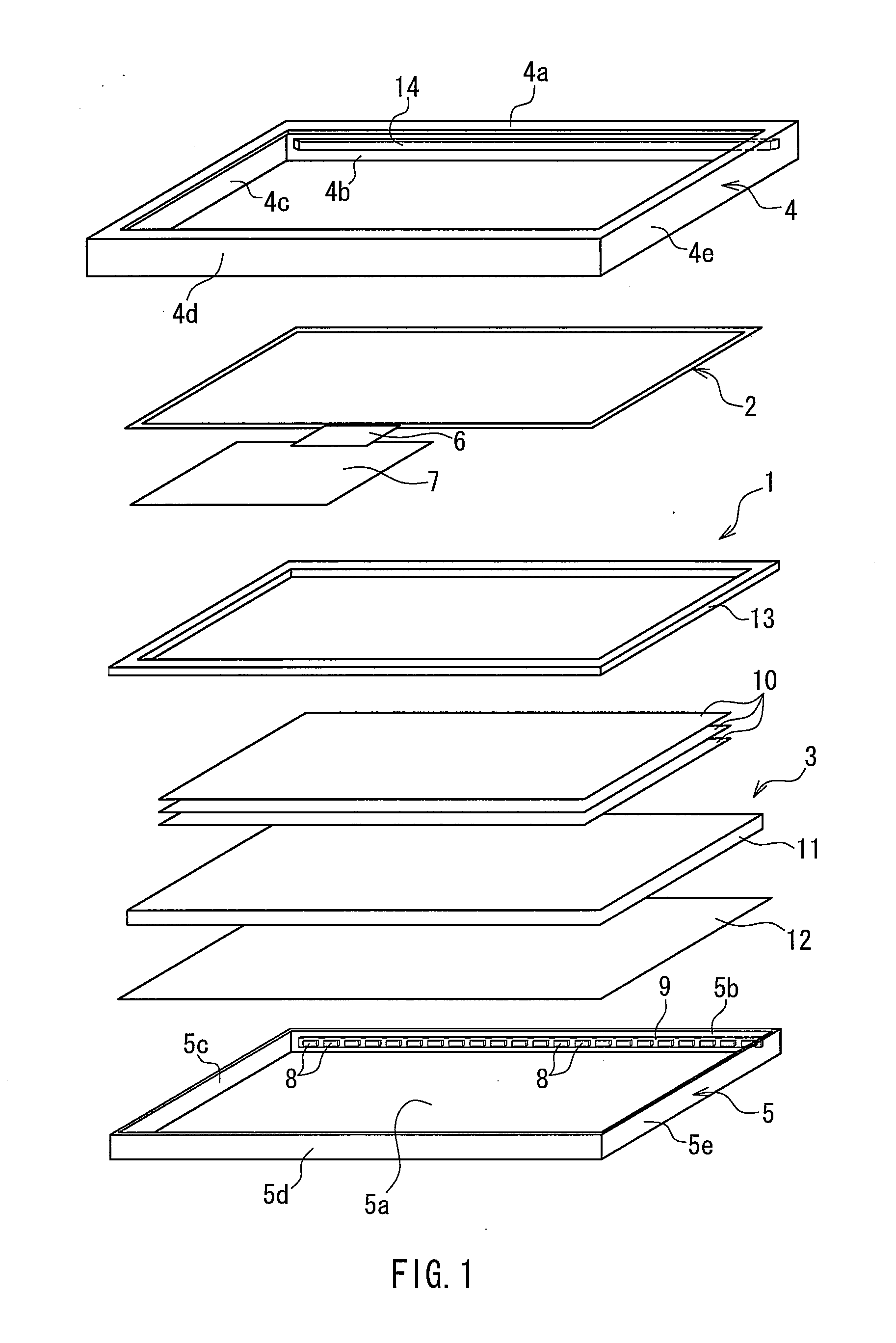
[0034]FIG. 1 is an exploded perspective view for explaining the configuration of a liquid crystal display apparatus according to Embodiment 1 of the present invention. In FIG. 1, the liquid crystal display apparatus 1 of the present embodiment includes a liquid crystal panel 2 as a display portion for displaying information and an illuminating device 3 for irradiating the liquid crystal panel 2 with illumination light. The liquid crystal panel 2 and the illuminating device 3 are combined into the transmission-type liquid crystal display apparatus 1. That is, the liquid crystal display apparatus 1 includes, as an outer casing for accommodating the liquid crystal panel 2 and the illuminating device 3, a bezel 4 provided on the liquid crystal panel 2 side and a frame 5 provided on the illuminating device 3 side. The constituent members of the liquid crystal display apparatus 1 shown in FIG. 1 are stacked together and are accommodated between the bezel 4 and the frame 5.
[0035]The bezel ...
embodiment 2
[0046]FIG. 5 is a plan view for explaining the main configuration of a liquid crystal display apparatus according to Embodiment 2 of the present invention. FIGS. 6(a) and 6(b) are a perspective view and a plan view for explaining the main configuration of the bezel shown in FIG. 5, respectively. FIGS. 6(c) and 6(d) are cross-sectional views taken along the line VIc-VIc and the line VId-VId in FIG. 6(b), respectively. In the drawings, the primary difference between the present embodiment and Embodiment 1 is that in the present embodiment lugs are formed on one side surface of the bezel and holes are formed in the side wall of the frame opposing the side surface and the lugs are fitted into the holes. Note that the same elements as in Embodiment 1 are denoted by the same reference numerals and the description thereof will not be repeated.
[0047]That is, as shown in FIG. 5 and FIGS. 6(a) to 6(d), in the liquid crystal display apparatus 1 of the present embodiment, a plurality of the lig...
embodiment 3
[0051]FIG. 7 is a plan view for explaining the main configuration of a liquid crystal display apparatus according to Embodiment 3 of the present invention. FIG. 8 is a cross-sectional view for explaining the main configuration of the liquid crystal display apparatus shown in FIG. 7. In the drawings, the primary difference between the present embodiment and Embodiment 1 is that a thermally conductive member is used in the present embodiment as the thermally conductive portion. Note that the same elements as in Embodiment 1 are denoted by the same reference numerals and the description thereof will not be repeated.
[0052]That is, as shown in FIGS. 7 and 8, in the liquid crystal display apparatus 1 of the present embodiment, the thermally conductive member 18 is disposed between the side surface 4b of the bezel 4 and the side wall 5b of the frame 5. For the thermally conductive member 18, a thermally conductive sheet or thermally conductive double-sided tape having thermal conductivity ...
PUM
 Abstract
Description
Claims
Application Information