
Glass processing apparatus and method

A processing device, glass technology, applied in metal processing equipment, manufacturing tools, machine tools suitable for grinding the edge of workpieces, etc.

Inactive Publication Date: 2008-11-12
SEONGHYUN TECH
View PDF0 Cites 8 Cited by
  • Summary
  • Abstract
  • Description
  • Claims
  • Application Information

AI Technical Summary

Problems solved by technology

[0006] Recently, automatic tool exchange systems that automatically exchange tools according to the characteristics of the object to be processed in a continuous processing process tend to be widely used in response to the preferences of consumers. , but since the cleaning process of tool holders and tools is carried out separately from the processing process before and after the processing process as described above, it has not yet solved the difficulty of properly combining with the automatic tool exchange system to perform cleaning processing quickly
[0007] And, as the machining process after the exchange is continuously performed in a state where the tool holder or the tool is contaminated by chips or other machining products generated in the machining process before the exchange of the tool, after separating the tool from the tool holder and moving the tool holder to the In the process of clamping again on the other tool side, the pollution and error range of the tool holder and tool will be further aggravated and expanded, which not only affects the life of the tool holder and tool, but also makes the machining accuracy drop sharply

Method used


Image

  • Glass processing apparatus and method
  • Glass processing apparatus and method
  • Glass processing apparatus and method

Examples


Embodiment Construction

[0030] Hereinafter, the present invention will be described in detail with reference to the drawings.

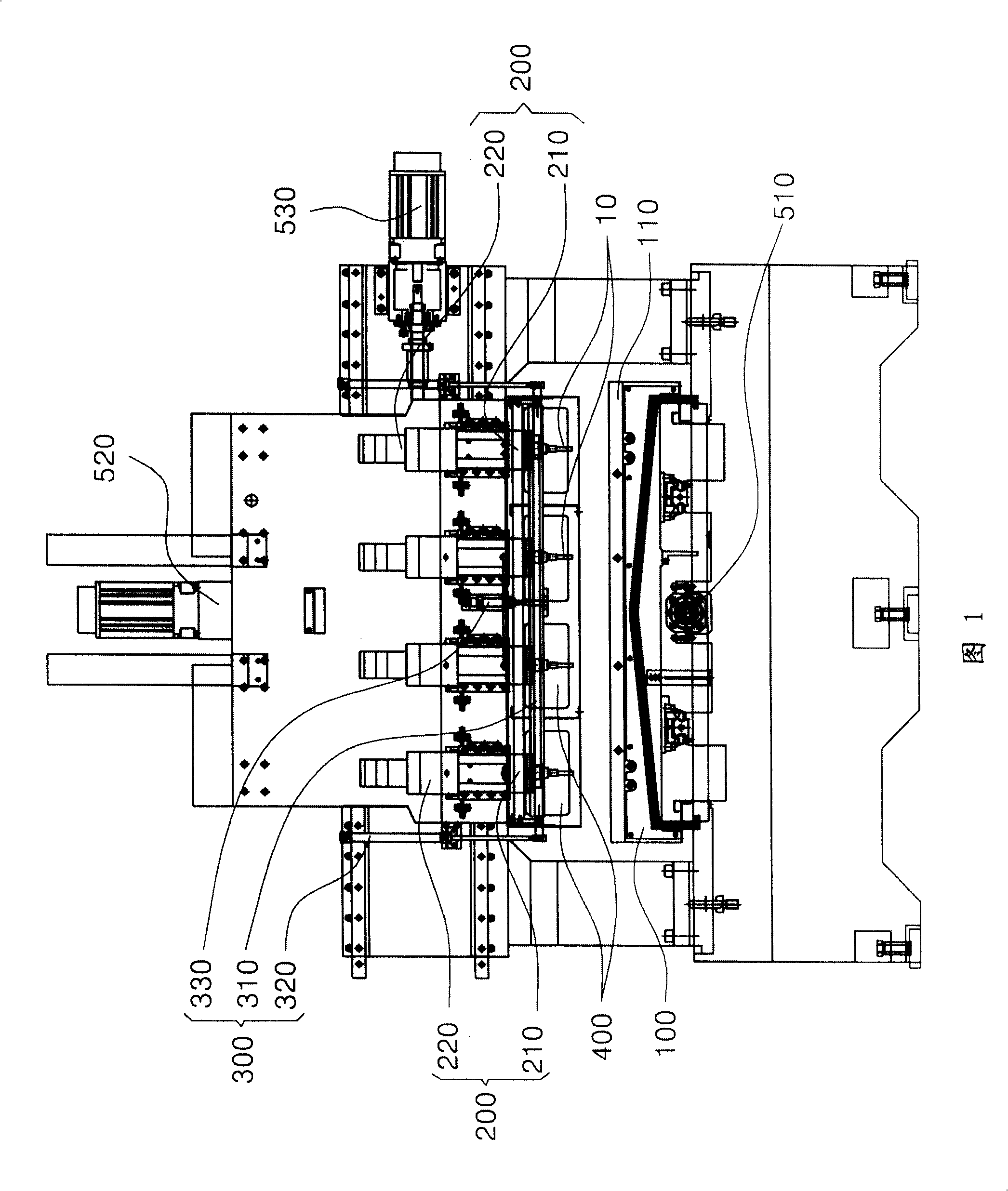
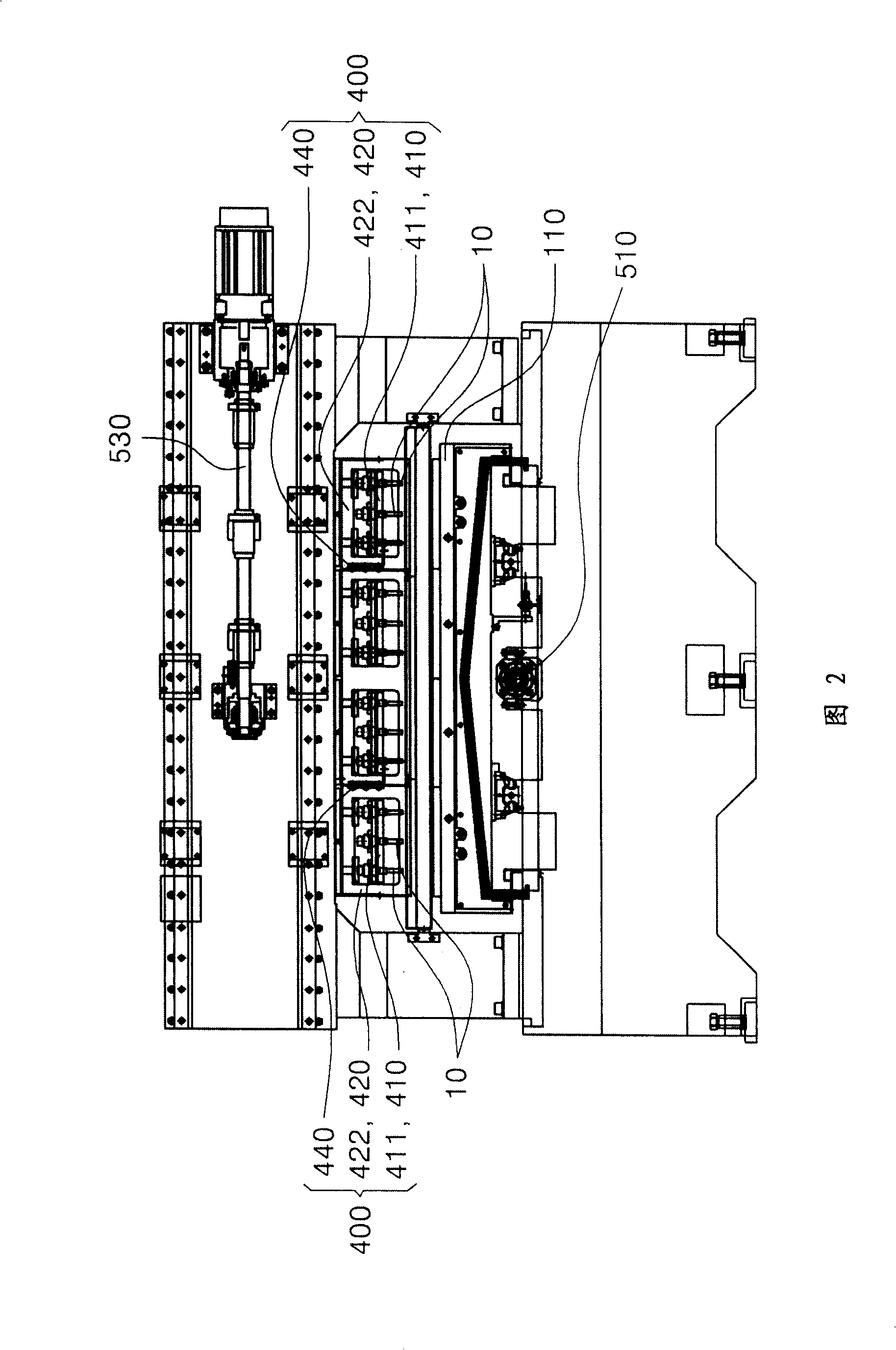
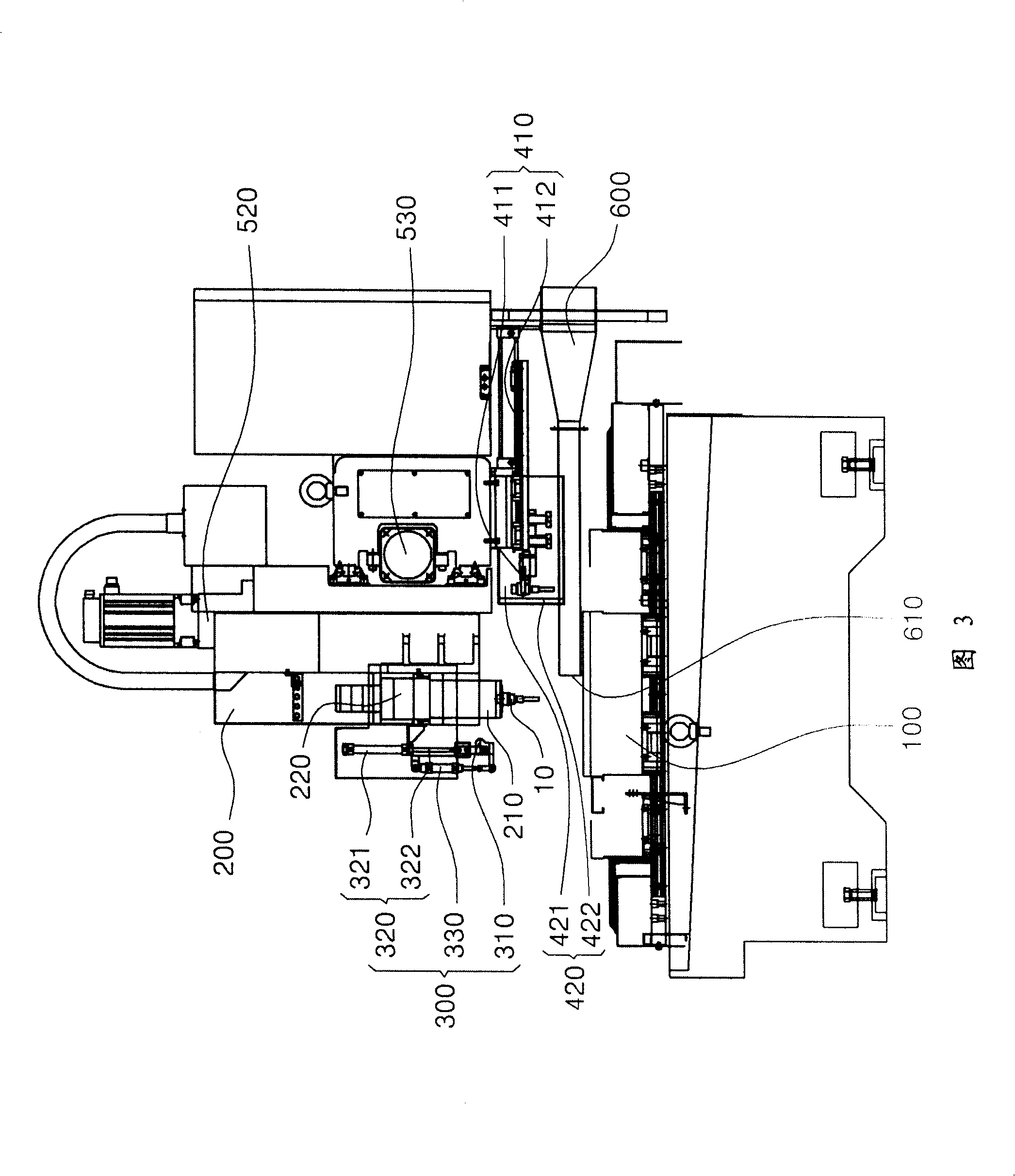
[0031] Fig. 1 is a front view of the first embodiment of the glass processing device provided by the present invention, Fig. 2 is a front view of main parts of the automatic tool exchange part, Fig. 3 is a right side view of Fig. 1, Figure 4It is the rear view of the main part of the longitudinal section of the auxiliary container, Figure 5 Fig. 6 is a plan view of the tool changer, which is a right side view of the main part showing the angle adjustment of the air knife part. Figure 7 To show the main part right side view showing the case opening and closing state by the movement of the tool changer, Figure 8 It is a flowchart showing the first embodiment of the glass processing method provided by the present invention.

[0032] The glass processing device provided according to the present invention is roughly composed of a table part 100, a tool rotating part 200, an ...


PUM


Abstract

This invention relates to a glass processing device and processing method. The glass processing device comprises: a working table part for installing and fixing the processed object of glass material; a tool rotary part including a tool clamp for installing tools and a spindle motor for rotating the tool clamp and processing the processed object of glass material through the relative movement with the working table part; an air knife part lifting and moving the upper and lower parts of the tool rotary part and jetting high-pressure air to a tool mounting part of tool clamp and the lower end of the tool of the tool clamp; an automatically changing part of tools which is provided with multiple sharpeners and is installed at the lower side of the tool rotary part, and is used for automatically changing sharpeners installed at the tool clamp through moving to the internal and external parts of the moving path of the tool clamp. This invention can more quickly and easily clean through properly jetting and adjusting the high-pressure air based on properly combining the tool rotary device, the air knife and the automatically changing part of tools.

Description

technical field [0001] The present invention relates to a glass processing device and a glass processing method, and more particularly to a glass processing device and a glass processing method for processing an object to be processed fixed on a table by transferring a high-speed rotating tool along a predetermined path. Background technique [0002] Usually, the processing method of cutting flat glass (sheet glass) into a small predetermined shape includes a method of moving along the cutting line while pressing the glass on the upper side of the glass plate at a certain frequency. How can meet a certain quality. However, when grinding a thin side surface of a glass material cut into a small size, since the contact area between the grinding tool and the glass plate varies depending on the shape of the glass plate to be processed, it is difficult to ensure constant quality. [0003] Grinding refers to the process of grinding rough surfaces into smooth surfaces by contacting...

Claims


Application Information

Patent Timeline
IPC IPC(8): B24B9/08B24B41/02B24B41/04
CPCB24B5/10B24B9/08
Inventor 金洛泫
Owner SEONGHYUN TECH
Learn More