
Optical background module set and its fixing mechanism

A backlight module and fixing mechanism technology, applied in optics, nonlinear optics, instruments, etc., can solve problems such as unstable assembly quality, failure to pass the impact test of the backlight module, and viscous deterioration, so as to avoid the rupture of the lamp tube , Improve the display quality, improve the effect of stability

Active Publication Date: 2007-09-26
AU OPTRONICS CORP
View PDF4 Cites 0 Cited by
  • Summary
  • Abstract
  • Description
  • Claims
  • Application Information

AI Technical Summary

Problems solved by technology

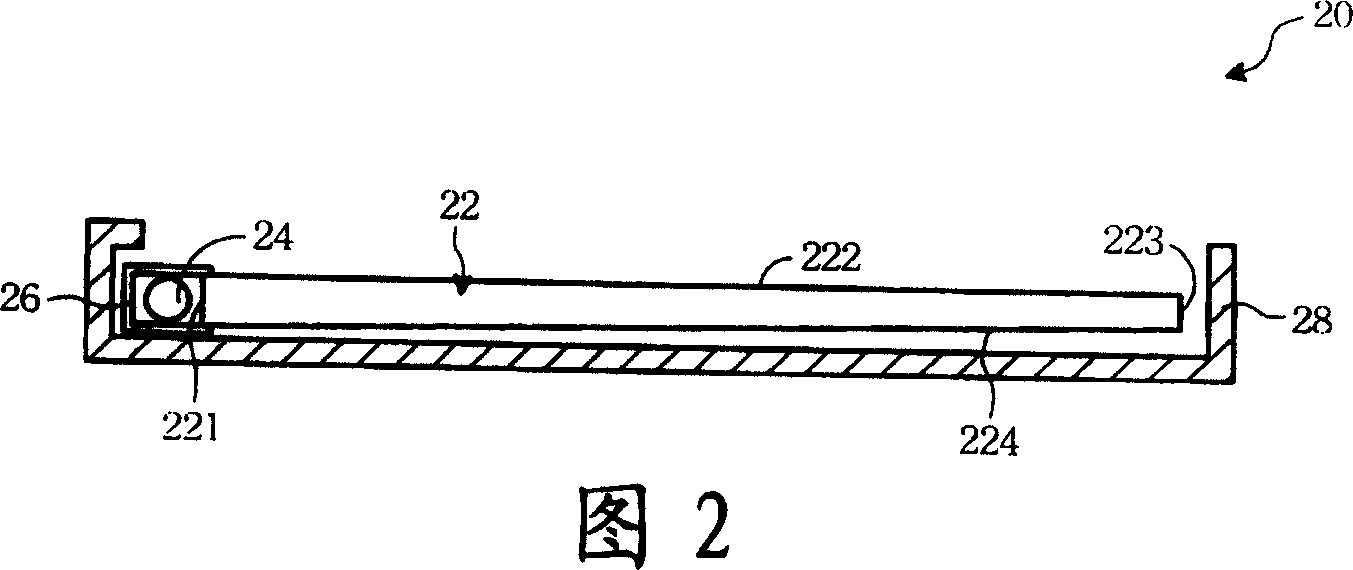
However, due to the current quality control standards for products with increasingly strict shock resistance requirements, such an assembly method often fails to pass the impact test before the backlight module leaves the factory. And cause the rupture of lamp tube 34 or the damage of light guide plate 32 itself
[0017] When the liquid crystal display is in use, the backlight module 32 is mostly erected in an upright manner as shown in FIG. In addition, if the double-sided tape 45 is placed in the high-temperature environment of the backlight module for a long time, its viscosity will gradually deteriorate.
These unstable factors in the quality of assembly are all the shortcomings of the second known technology that still need to be improved.

Method used


Image

  • Optical background module set and its fixing mechanism
  • Optical background module set and its fixing mechanism
  • Optical background module set and its fixing mechanism

Examples


Embodiment Construction

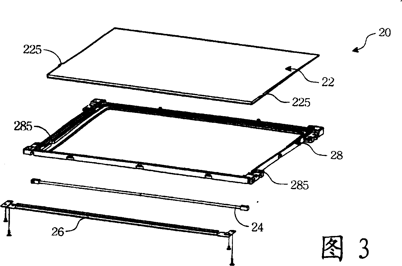
[0045] Please refer to FIG. 6 , which is an exploded perspective view of the backlight module of the present invention. The backlight module 50 includes a light guide plate 52 , a light tube 54 , a lampshade 56 and a frame 58 . The light guide plate 52 has an incident end 521 , a light output surface 522 , a front end 523 and a bottom surface 524 .

[0046] The light guide plate 52 is made of light-permeable acrylic material by injection molding, and is disposed on the frame 58 , and its bottom surface 524 corresponds to the frame 58 . The bottom surface 524 of the light guide plate is provided with a plurality of particle patterns, and its main function is to scatter or reflect light inside the light guide plate 52, so that the light can be evenly output from the light exit surface 522, such as the V pattern used in the preferred embodiment of the present invention. -cut type light guide plate, that is to use a special scraper to form a microstructure of V-shaped grooves on ...


PUM


Abstract

A fixing mechanism including bead and containing groove features that bead is set at bottom face of light guide plate, groove corresponding to bead is set on frame. A photonegative module incluidng a light guiding plate, a frame and a light source is featured as fixing light guiding plate on frame for placing bead into groove in crease stability of photonegative module.

Description

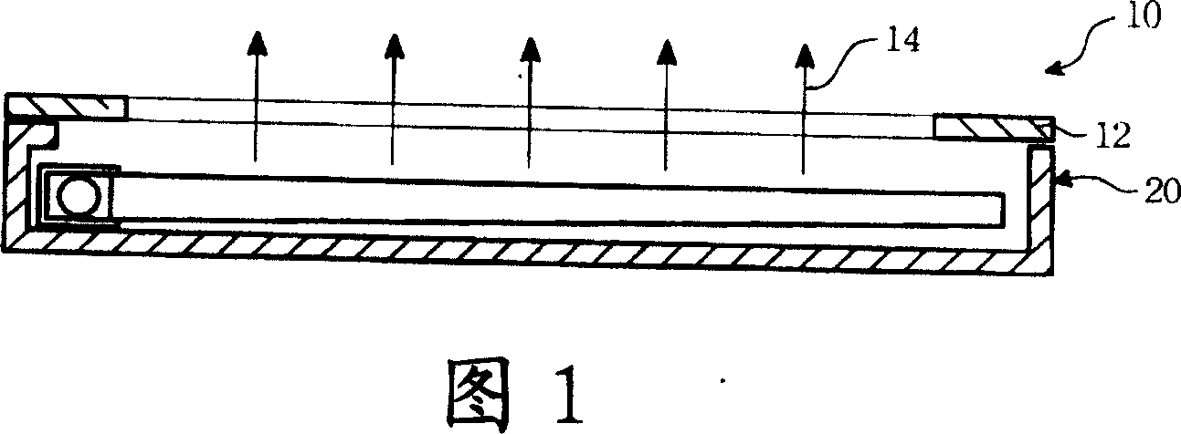
technical field [0001] The invention relates to a backlight module and its fixing mechanism. Background technique [0002] Please refer to FIG. 1 , which is a basic diagram of a known liquid crystal display. The liquid crystal display 10 includes a glass substrate 12 and a backlight module 20 . [0003] The glass substrate 12 is a non-luminescent display element, which needs to be provided with a backlight by the backlight module 20 behind it to display. As shown in FIG. 1 , the light 14 is provided to the glass substrate 12 by the backlight module 20 . The inside of the glass substrate 12 has a liquid crystal layer and a color filter layer. The glass substrate 12 determines the brightness of the light by the alignment direction of the liquid crystal molecules in the liquid crystal layer, and the color of the light output is determined by the color filter layer. [0004] The brightness of the backlight module 20 is generally sufficient in current technologies, and the unif...

Claims


Application Information

Patent Timeline
Patent Type & Authority Patents(China)
IPC IPC(8): G02F1/1335
Inventor 杨孝德
Owner AU OPTRONICS CORP
Learn More