Composite cable comprehensive pipe rack and constitutional unit thereof

A technology of integrated pipe gallery and composite cable, applied in cable installation, cable installation in tunnels, water conservancy projects, etc., can solve the problems of difficult maintenance, long construction period, serious water inflow, etc. Short cycle, easy to build effect

Pending Publication Date: 2019-03-29
WUXI JIABANG ELECTRIC POWER PIPE FACTORY
View PDF0 Cites 0 Cited by
  • Summary
  • Abstract
  • Description
  • Claims
  • Application Information

AI Technical Summary

Problems solved by technology

The cross-section of the square pipe gallery is rectangular. This kind of pipe gallery has the following defects: 1) poor practicability and unreasonable division of warehouses; 2) poor load-carrying performance at the top and overall anti-settling performance; 3) anti-settling performance of the pipe gallery interface Poor leakage performance
The pipe gallery with a circular or arched cross-section has relatively better structure, but it also has defects: under the same height and width restrictions, the interior space of the pipe gallery is small, whether it is installing pipelines or post-processing maintenance, operation is inconvenient
Due to the space occupied by the installation bracket 2' and the existence of the necessary passageway 4', the number of cables 3' that can actually be installed in the pipe gallery 1' is extremely limited, and a large number of installation brackets 2' also increases the cost
[0004] In addition, the quality of the reinforced concrete pipe gallery is not easy to control, the construction period is long, the seismic performance is low, the impermeability and waterproof performance are poor, and the internal water ingress is serious after long-term use, making maintenance difficult

Method used


Image

  • Composite cable comprehensive pipe rack and constitutional unit thereof
  • Composite cable comprehensive pipe rack and constitutional unit thereof
  • Composite cable comprehensive pipe rack and constitutional unit thereof

Examples


Embodiment Construction

[0025] The technical solutions of the present invention will be further described below in conjunction with the accompanying drawings and through specific implementation methods.

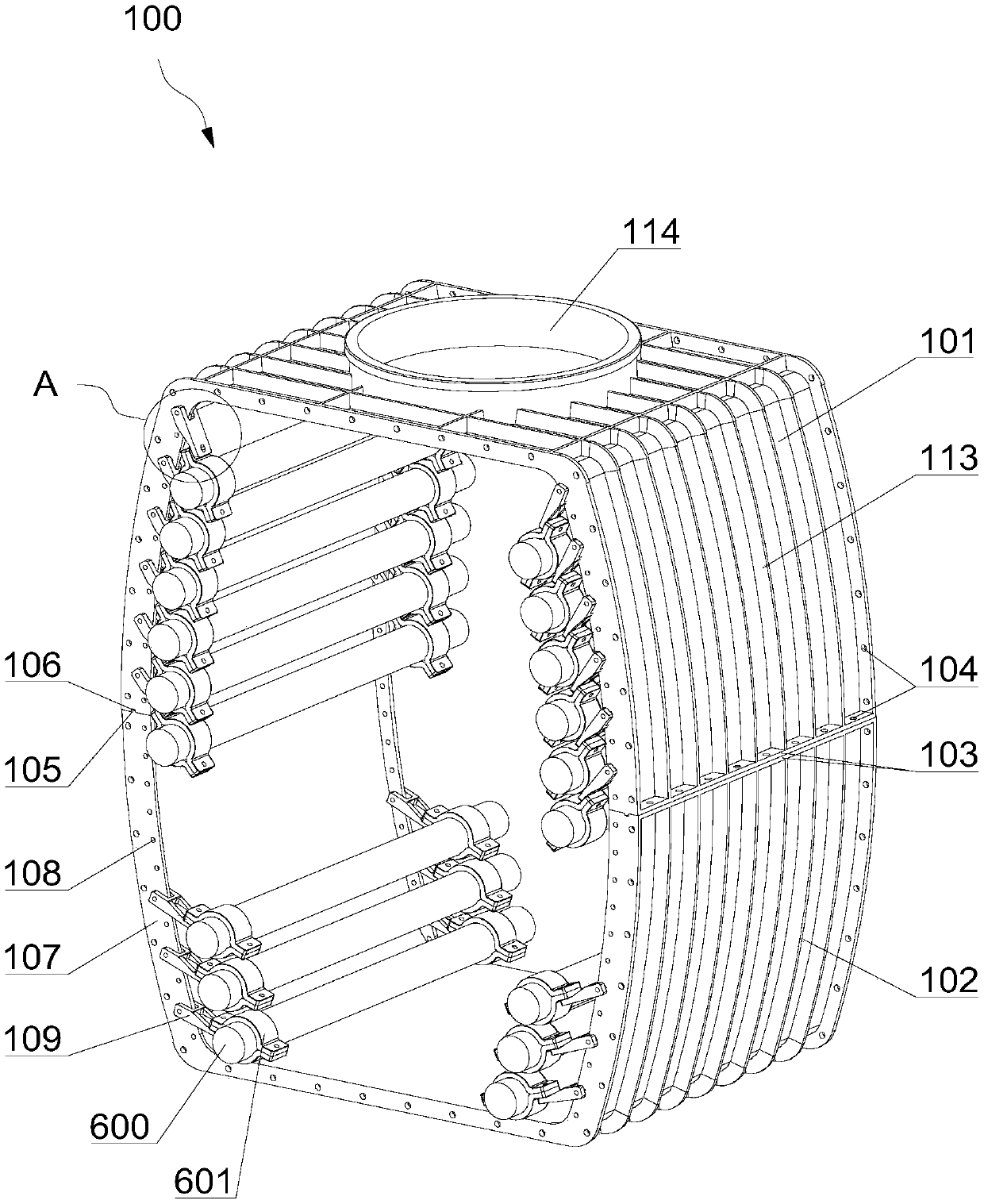
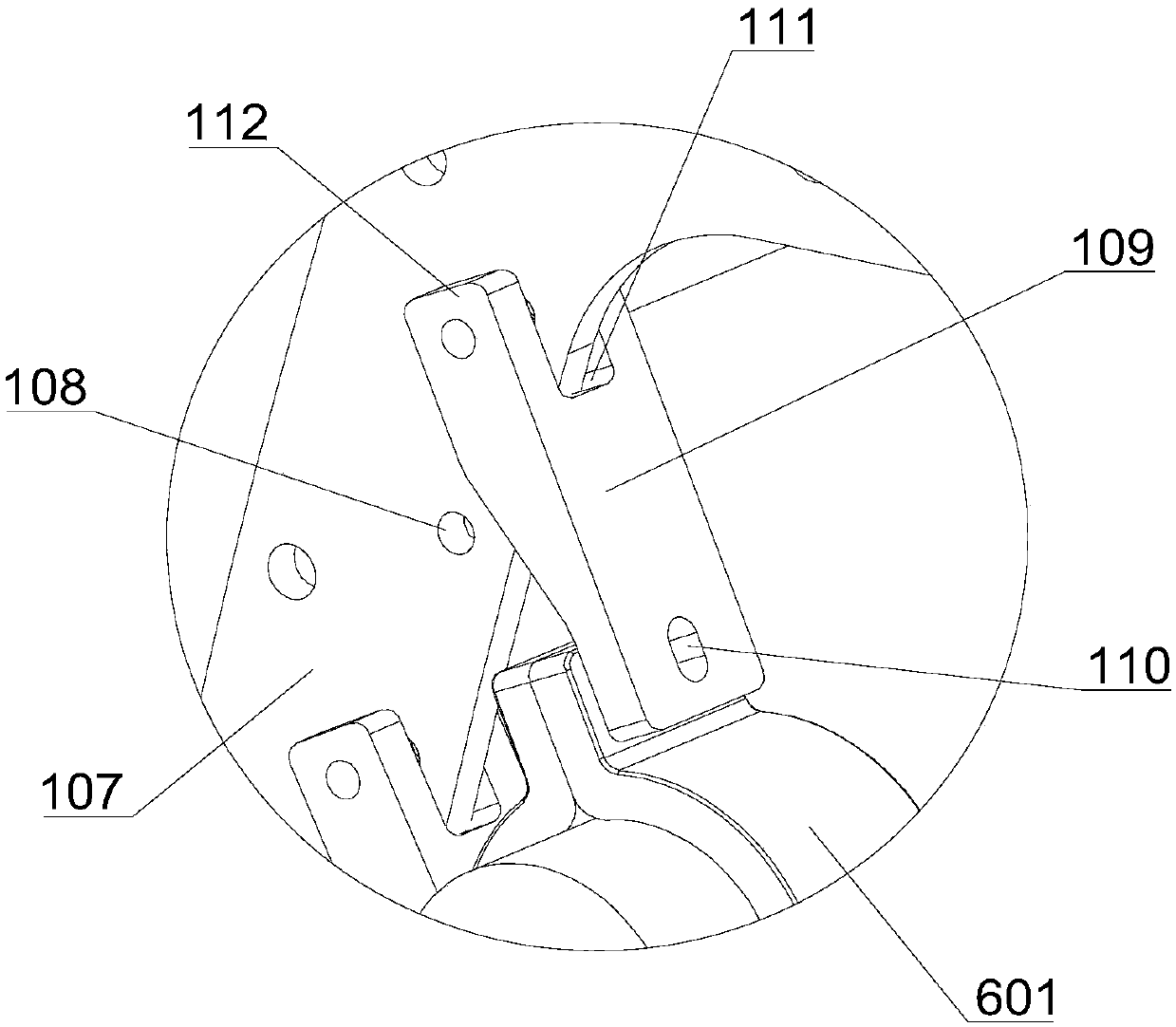
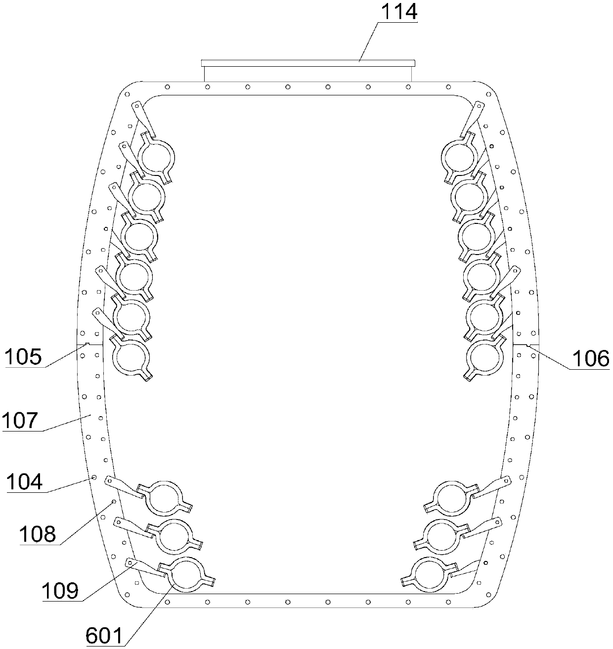
[0026] see Figures 1 to 5 As shown, this embodiment provides a composite cable integrated pipe gallery unit 100, which mainly includes an upper body part 101 and a lower body part 102, and the upper body part 101 and the lower body part 102 are combined to form a pipe gallery unit cabin. The upper body part 101 and the lower body part 102 have symmetrical structures, and both include a middle plane wall and two arc-shaped walls.

[0027] An inspection port 114 can be opened on the plane wall of the upper body 101, and a manhole cover 500 is arranged on the inspection port 114, which is convenient for personnel to enter and exit for maintenance. The plane wall of the lower body part 102 is convenient for people to walk around.

[0028] The arc-shaped pipe wall formed by the combination has a good ...


PUM


Abstract

The invention discloses a composite cable comprehensive pipe rack unit which comprises an upper body part and a lower body part. The upper body part and the lower body part are combined to form a piperack unit cabin, the side face edges of the upper body part and the lower body part are each provided with an installing edge linked with the adjacent units, the installing edges protrude out of theinner walls of the upper body part and the lower body part, a plurality of suspension holes are formed in the portions protruding out of the inner walls, and damping holding hooks are arranged in thesuspension holes and fixed to a cable clamp hoop. According to the composite cable comprehensive pipe rack unit, the mode that a cable is suspended along the inner wall is adopted, an installing support is omitted, the pipe rack internal structure is reasonably arranged, the operation space is enlarged, the damping holding hooks are convenient and reliable to install, and enough shock resistance is given to the cable. The invention further provides a composite cable comprehensive pipe rack which is formed by combining and constructing pipe rack units. Due to the unit combination mode, the comprehensive pipe rack is easier and more flexible to build, the adaptability is high, the construction period is short, and the new thought is provided for pipe arrangement.

Description

technical field [0001] The invention relates to the technical field of cable pipe gallery structures, in particular to a composite cable comprehensive pipe gallery and its constituent units. Background technique [0002] The comprehensive pipe gallery is a public tunnel for the centralized laying of municipal pipelines such as electricity, communications, radio and television, and water supply. The pipe gallery is generally laid underground, and the underground comprehensive pipe gallery mostly adopts square pipe gallery or circular pipe gallery. The cross-section of the square pipe gallery is rectangular. This kind of pipe gallery has the following defects: 1) poor practicability and unreasonable division of warehouses; 2) poor load-carrying performance at the top and overall anti-settling performance; 3) anti-settling performance of the pipe gallery interface The leakage performance is poor. The pipe gallery with a circular or arched cross-section has relatively better s...

Claims


Application Information

Patent Timeline
IPC IPC(8): E02D29/045H02G9/08
CPCH02G9/08E02D29/045E02D29/10
Inventor 徐德生徐涛
Owner WUXI JIABANG ELECTRIC POWER PIPE FACTORY
Why Eureka
Try Eureka