
Device for making artificial snow

A technology for artificial snowmaking and equipment, applied in lighting and heating equipment, ice making, recreational ice making, etc., can solve the problems of reducing icing efficiency

Inactive Publication Date: 2007-10-31
金主植
View PDF9 Cites 1 Cited by
  • Summary
  • Abstract
  • Description
  • Claims
  • Application Information

AI Technical Summary

Problems solved by technology

The disadvantage of this structure is that the icing efficiency is reduced because the evaporation temperature is not directly transmitted to the hot and cold plates
[0004] Also, since the conventional ice cutting blades are angled at one point relative to the vertical, it is difficult to chip the ice to produce artificial snow similar to natural snow

Method used


Image

  • Device for making artificial snow
  • Device for making artificial snow
  • Device for making artificial snow

Examples


Embodiment Construction

[0023] Preferred embodiments of the present invention are described below with reference to the accompanying drawings. In the following description, in order to avoid redundancy, some well-known functions and structures will not be described in detail.

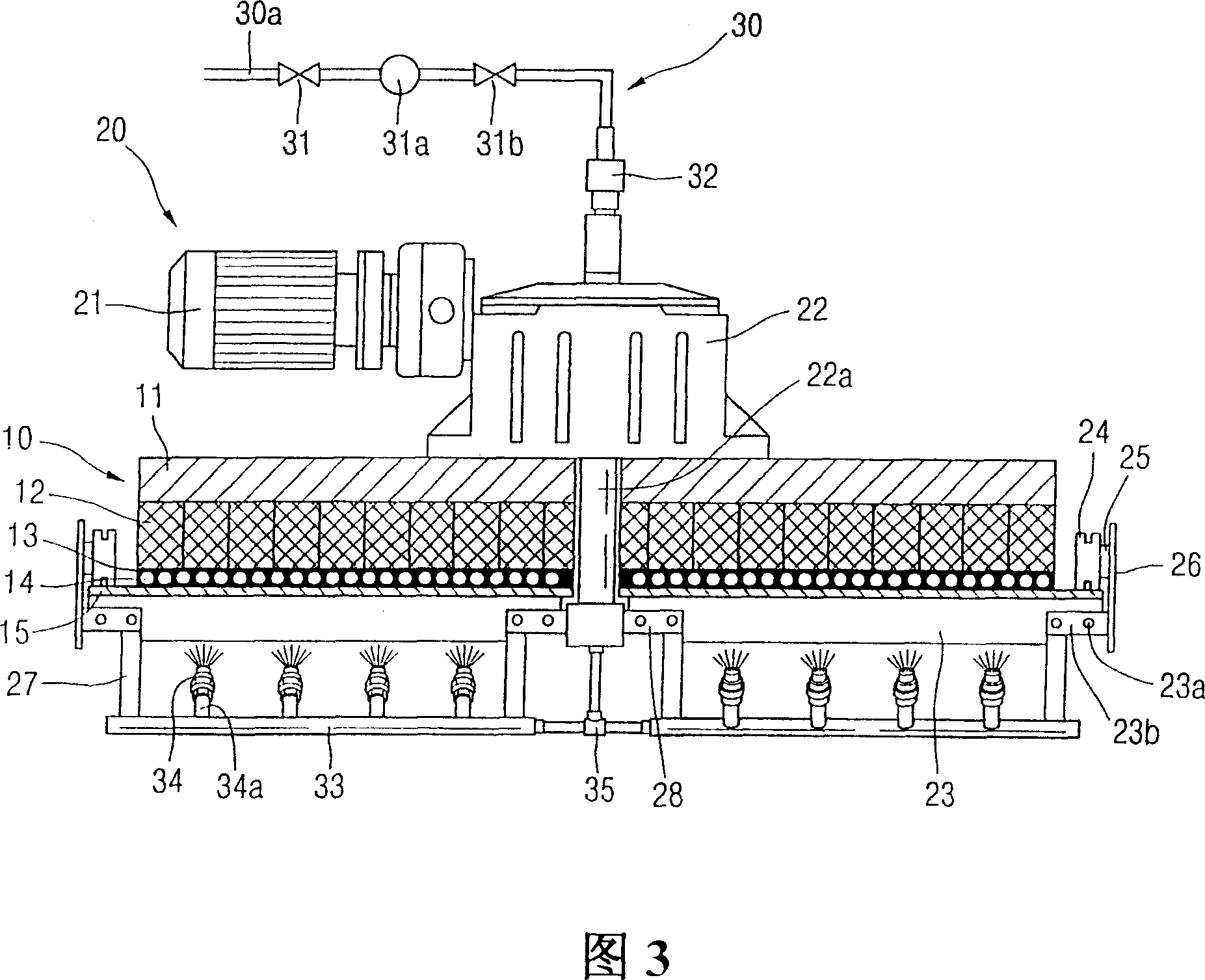
[0024] The artificial snowmaking equipment according to the present invention comprises a hot and cold plate 10 having a chassis 11, a thermally conductive material 13 filled outside the evaporation line 14, and an icing plate 15, a cutting unit comprising a motor 21, a reduction gear 22, a blade 23 and a roller 24 20, and a water supply unit 30 comprising a pump 31a, a swivel joint 32 and a distribution line 33 equipped with a nozzle 34. The artificial snow making equipment further includes an automatic door device on the lower surface of the hot and cold plate unit 10 .

[0025] Referring to FIG. 3 , the artificial snowmaking equipment includes a hot and cold plate unit 10, which includes a chassis 11 on which a heat insula...


PUM


Abstract

A device for making artificial snow is provided, which includes a cold-heated plate unit including a bottom plate, a heat transfer material filling the outside of an evaporation line, and a freezing plate; a crushing unit including a motor, a reduction gear, a blade and a roller; and a water supply unit including a pump, a rotary joint and a distribution line equipped with nozzles. An automatic door device is added if necessary. The heat transfer material is injected between the evaporation line and the freezing plate so as to obtain a structure in which evaporating temperature is directly transferred to the cold-heated plate, thereby allowing for manufacture of a wide cold-heated plate having the desired shape. The blade is inclined twice so as to reduce a frictional heat generated from the cut snow and permit the ice formed at the surface of the freezing plate to be cut in an efficient manner.

Description

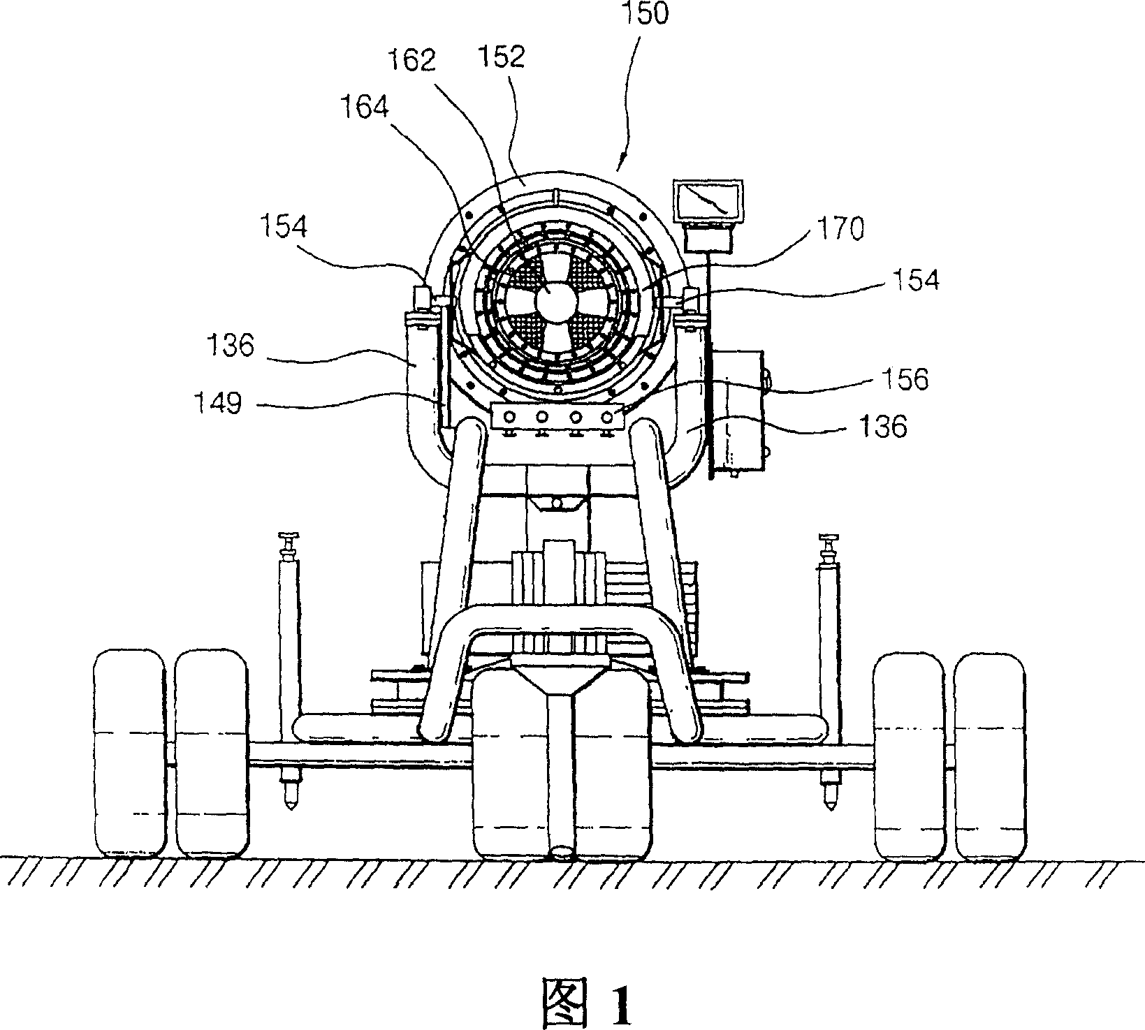
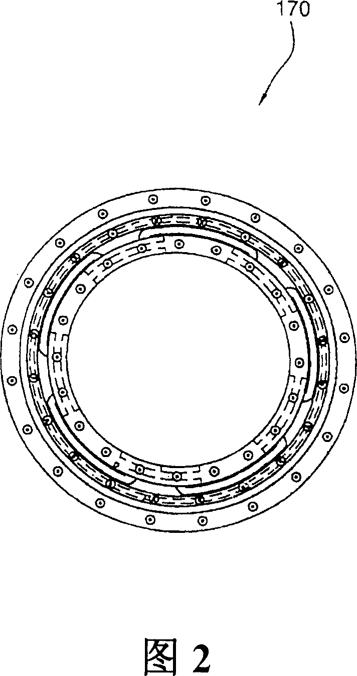
technical field [0001] The present invention relates to an artificial snow making device, in particular to a snow making device for producing artificial snow for ski slopes. Background technique [0002] As shown in Fig. 1 and Fig. 2, the inventor of the present invention disclosed a kind of artificial snow making equipment in Korean Utility Model Patent Registration No. 162 and manifold 170 . The main body has a hollow cylindrical shape and its front surface extends and narrows in the radial direction. There are rotation shafts 154 mounted on the upper supports 136 on both side surfaces of the main body. An extension portion of the angle adjuster 149 extending from the upper support is fixed to the main body, and a liquid supply unit 156 is provided under the main body 152 . One end of the liquid supply unit 156 is provided with a plurality of connection pipes controlled by a plurality of valves and connected to the manifold 170, and a supply pipe for supplying water fro...

Claims


Application Information

Patent Timeline
Patent Type & Authority Patents(China)
IPC IPC(8): F25C3/04
CPCF25C2500/02F25C3/04F25C2303/048
Inventor 金主植
Owner 金主植
Learn More